

RF and microwave multifunction boards are getting more complicated, while development schedules are getting shorter to meet time-to-market requirements. In this evolving development process, there is usually not enough time to test the individual blocks, and the feasibility for full deterministic analysis of the whole board is low, especially in terms of EM/cross-talk simulation.
The ability to perform broadband, accurate and reliable in-circuit testing offers an opportunity to gain insight into the performance of individual blocks and sub-circuit chains under real environment conditions (loading, grounding, radiation, noise conduction, thermal dissipation and spectral purity, for example). This enables fast debugging and shorter development cycles, which in turn leads to shorter time-to-market and higher yield (that is lower costs) in production.
The definition of test points within the initial layout, using predefined footprints for proper in-circuit testing (no impact of footprints over performance and no need for source/load disconnection), enables fast and accurate in-circuit measurements and characterization.
The RealProbe family of accurate RF and microwave in-circuit testing probes was specially developed by Vectria Ltd. to enable all these measurements up to 7 GHz, for both absolute and relative frequency and time domain measurements, using any measurement equipment.
Adequate In-circuit Probes

Fig. 1 RealProbe VEC-102 coupling factor (measured using ANRITSU 37347C VNA).
To perform adequate in-circuit probing, the probe should have a high input impedance in order to avoid loading of the circuit tested, proper grounding and inner equalization in order to enable broadband flat and accurate coupling. The probe output should be matched to 50 ?, using a high frequency connector (SMA or similar) to enable flat and accurate interface to most common test equipment. The probe should also be DC-blocked to avoid DC loading of the tested circuit, and must have a high input power capability to avoid nonlinear performance. The RealProbes are compact passive probes (see Table 1) delivering all of these characteristics and featuring:

• High accuracy and flat frequency response from 10 MHz to 7 GHz (see Figure 1).
• Probing (coupling) factor: 25 ±0.5 dB nominal.
• Input power: 2 W avg., 25 W peak, 30 V DC.
• High impedance, negligible effect on circuitry.
• Integrated matched ground returns.
• Self-aligning independent height contacts.
• DC-blocked input and output.
• SMA 50 ? matched output to 7 GHz.
• Defined test point footprints (no impact on tested circuit down to 12 mil traces) (see Figure 2).
• Optional calibration jig for highest accuracy absolute power measurements (see Figure 3).
• Optional adapted flexible cables for ease of use and connection to various test equipment.
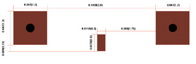
Fig. 2 RealProbe minimal test point footprint.

Fig. 3 RealProbe accesories.
Specific In-circuit Testing Applications
There are numerous applications for in-circuit testing within multifunction RF and microwave boards, starting from the obvious block’s gain measurements, up to time domain and EVM measurements. The following are a few examples of the probe capabilities:
• Accurate sub-channels gain measurements.
• Accurate in and out power measurements of the transmit stages within the line-up, identifying compressed stages, etc.
• Low to high power measurements over the board, up to 25 W peak and 2 W average power.
• Accurate local oscillator power measurement.
• Internal mid-channel spurious detection.
• LO leakage that is masked by filters later on in the chain and can saturate earlier stages.
• IF/RF/microwave sub-channel performance measurement.
• Real filter rejection within the chain.
• In-channel time domain measurements for analog and fast digital signals under real source and load conditions.
• The ultimate tool for “finding” the last missing decibels in a long chain.
• Fast repair of multifunction RF and microwave boards.
• In-circuit delay, compression, and EVM measurements using signal and network analyzers.
Measurements and Calibration Procedures
Basic Measurements
This is the fastest mode of measurement in which probing is performed directly on the desired test point and the coupling factor (25 dB) is added to the measured power/voltage amplitude.
Best Power Measurements Accuracy Using a Calibration Jig
This is the most accurate absolute power testing that calibrates all the following error factors at the frequency of interest: probe coupling, output cable, test equipment deviation (spectrum analyzer, for instance). In this procedure, the optional calibration jig is used. This jig is based on a short, coplanar line, with in and out SMA connectors, having a test point footprint in its center. The basic idea is to inject a signal with a known power (preferably calibrated by a power meter) to the calibration jig with its output terminated, then probing the test point using the RealProbe and output cable to the test equipment (spectrum analyzer, for instance), and deriving the correction factor using the following equation:
CF = P in – (Pmeasured + HWJL)
where
HWJL = half way jig loss at the specific frequency, as defined by the jig data
CF = correction factor at the specified frequency
The in-circuit measurement is then accomplished using:
Pprobed = Pmeasured + CF
Gain Measurements Using a Network Analyzer
There are two major methods for gain measurements using a network analyzer. The first method involves a test point to another test point gain measurement. In this method, the signal is injected at the relevant circuit external connector and the tested block is probed at the input test point, saving the results in memory. The tested block output is then probed using the data/memory display.
The second method is a coaxial input to in-circuit test point chain measurement. In this method, the RealProbe calibration jig is used for calibrating a through path by injecting the network’s port 1 to the calibration jig (terminated at the other end), and connecting the network’s port 2 to the probe’s output cable while probing the calibration jig test point, then saving the through or S21 measurement to memory. For the measurement itself, the signal is injected to the relevant circuit external input connector, and probing the tested sub-chain output using the data/memory display.
Conclusion
The ability to perform a broadband accurate and reliable in-circuit testing offers an opportunity to gain insight into the individual blocks and sub-circuit chains performance under real environment conditions. This enables fast debugging and shorter development cycles, which in turn leads to shorter time-to-market and higher yield (that is lower costs) in production. The RealProbe family of in-circuit probes, along with predefined test point footprints within the board layout, enables all of the above-mentioned measurements up to 7 GHz in a compact pocket size passive probe.
Vectria Ltd.,
Ashkelon, Israel,
+972-8-6724459,
www.vectria.co.il.