
In present-day wireless communication equipment, the need for antennas of high efficiency has generated much interest in the study of microstrip antennas. These printed microstrip antennas exhibit a low profile and are lightweight. However, microstrip antennas have inherently narrow bandwidths and, in general, are half-wavelength structures, operating in the TM01 or TM10 fundamental resonant mode.1 In the proposed design, printed isosceles triangular slot antennas, fed by microstrip-line structures, have been designed with improved bandwidth. The printed slot antennas offer the advantages of low profile, lightweight, low cost, wide bandwidth, conformability to a shaped surface and compatibility with integrated circuitry.2,3 In addition to these advantages, the design has another important point in that it has a simple feed structure, so it is suitable for many applications of wireless communication.
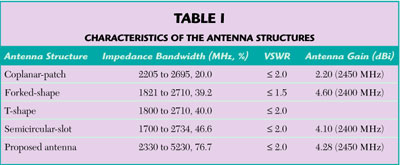
Researchers have made efforts to overcome the problem of narrow bandwidth in coplanar-patch antennas, and various configurations have been presented to extend the bandwidth. Adding a short on the upper slot of the coplanar-patch antenna and varying its length have achieved an impedance bandwidth of 30 to 40 percent4 at high frequencies for radar applications. However, conventional printed wide slot antennas have an operating bandwidth on the order of 10 to 20 percent.5 Hence, the broadband design of wide slot antennas has thrown new light on wireless communications. In recent years, several articles5–7 have been devoted to the study of some printed wide slot antennas for broadband operation (see Figure 1). Table 1 shows a comparison of the characteristics of these different antenna structures.
This article describes the investigation of the simple design of an isosceles triangular slot antenna for broadband operation. This new design consists of a microstrip-line-fed, printed isosceles triangular slot antenna with a small rectangular slot tuning for extended bandwidth. The radiation characteristics of such a design are also investigated. The microstrip-feed line used in the proposed design is different from the dual-offset microstrip-feed lines used for the excitation of an aperture-coupled patch antenna with a narrow coupling slot.8–12 Through proper selection of the parameters of the small rectangular slot, it can be expected that the coupling between the microstrip line and the isosceles triangular slot can be controlled more effectively, which makes possible the very broad band of the printed isosceles triangular slot antenna. Experiments show that the impedance bandwidth (VSWR £ 2) obtained for the proposed antenna can reach approximately 4.6 times that of a conventional microstrip-line-fed, printed isosceles triangular slot antenna with a simple tuning microstrip line.

Fig. 1 Structures of (a) fork-shaped microstrip-line-fed- antenna, (b) T-shaped microstrip-line-fed antenna and (c) semi-circular slot antenna.
Antenna Configuration
The configuration of the proposed antenna (called Antennas 2 and 4 in this design) is shown in Figure 2. The microstrip-line-fed, printed isosceles triangular slot antenna shows a small rectangular slot of dimensions L × W placed at the vertex of the isosceles triangular slot and centered above the microstrip-feed line. The isosceles triangular slot antenna is fed by a 50 ? microstrip line, printed on the opposite side of the substrate and placed on the centerline (y axis) of the isosceles triangular slot. The simple tuning microstrip line is composed of a straight section of length Lf2. The isosceles triangular slot has sides of length A and a flare angle a. The width of the tuning line is equal to that of the 50 ? microstrip line (Wf).

Fig. 2 Antenna structures; (a) with a slot, (b) without a slot.
By selecting the proper dimensions for these parameters (listed in Table 2), the proposed antenna shows a good impedance matching across a very broad band. The substrate is made of FR-4 material with a height h and a dielectric constant ?r. For comparison, the geometry of a microstrip-line-fed, printed isosceles triangular slot antenna without a small rectangular slot (called Antennas 1 and 3) is also shown.

Experimental Results and Discussion
The analysis was performed using the High Frequency Structure Simulator (HFSS) commercial computer software package from Ansoft Technologies, which is based on the finite element method (FEM) technique for arbitrary 3D volumetric passive devices. The simulation procedure was verified by comparison with the experimental results of the antenna’s return loss measured with an HP-8753E network analyzer. Figure 3 shows that the measured and simulated results of the proposed design are in good agreement.
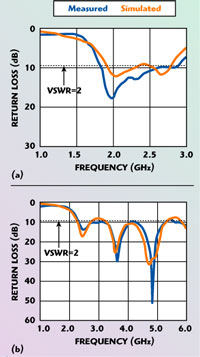
Fig. 3 Comparison of simulated and measured return losses; (a) Antenna 2, (b) Antenna 4
The first parameter under design was the flare angle ?. Its optimum value was found to be between 50° and 55°. From that numerical experiment, ?g can be calculated1

Table 3 shows ?g, ?o, ?reff and ?reff/?r for all of the proposed antennas designs. A comparison of the two tables shows that decreasing the base of the isosceles triangular slot (Lb) increases ?reff slightly.
Table 4 shows the lowest frequency fL and the highest frequency fH of operation and the impedance bandwidth BW (in MHz and percent) for all of the proposed antenna designs.
It is observed that these antennas can be used for different applications. Antenna 2 is suitable for GSM (1900 to 1990 MHz), PCS (1900 to 1990 MHz), IMT-2000 (1920 to 2170 MHz), Bluetooth (2400 to 2484 MHz), IEEE802.11 b/g (2400 to 2484 MHz), PHS (1905 to 1915 MHz), PACS (1930 to 1990 MHz) and UMTS (Regular 1, 2, 3). Antenna 4 is also suitable for Bluetooth, IEEE802.11 b/g, and even for operation in UWB (lower band, 3100 to 5150 MHz), IEEE802.11a (5150 MHz) and HIPERLAN/1/2 (5150 MHz).

By observing the influence of the various parameters on the antenna performance, it was found that the dominant factors in the proposed antenna designs are the base of the isosceles triangular slot in terms of ?g and the perimeter of the slot, defined as Lperimeter = 2(L + A) + W + Lb. By studying the given designs, it was clear that Lb was about 0.5?g and Lperimeter was about 2?gg. At the same time, the length of the tuning microstrip line (Lf2) in all designs was approximately 0.5?g, as shown in Table 5. In general, Lperimeter controls the resonant frequency while the base of the isosceles triangular slot and the dimensions of the tuning microstrip line control the level of the return loss and the bandwidth.
Further study revealed that the resonant frequency decreases when adding the dimension of the small rectangular slot and by decreasing the length of Lf1. Increasing ? decreases the impedance bandwidth, especially at the lowest frequency, such that ? has an optimal angle. A comparison of Tables 2 and 4 shows that the optimal angle is approximately 50°, leading to a broad bandwidth of the printed isosceles triangular slot antenna.
The proposed antenna was measured with an HP-8753E network analyzer. The measured return loss results of these design examples are shown in Figure 4. These results show that there are a number of reasons for Antennas 2 and 4 to have good impedance matching. One is a new resonant mode, in the vicinity of the fundamental resonant mode of the isosceles triangular slot antenna, which can be excited by a 50 ? microstrip line. Also, good impedance matching at both the fundamental and the new mode can be obtained, which leads to a very wide operating bandwidth of Antenna 4.

Fig. 4 Measured return loss of the proposed antennas.
There is one other thing that is important for broadband bandwidth. The size of the small rectangular slot determines the range of the lower frequency, while the length of the straight microstrip line determines the range of the higher frequency. By using the 50 W microstrip line-feed structure of Antenna 4, an impedance bandwidth of approximately 2.9 GHz (for a = 50°) can be obtained. The wider bandwidth of the Antenna 4 design can be greater than 1.7 times that of Antenna 2.
Note that a printed slot antenna without a reflecting plate is a bi-directional radiator, and the radiation patterns on both sides of the antenna are about the same. The proposed antenna shows the same characteristics. The radiation patterns were measured in the STUT Anechoic Chamber shown in Figure 5. Figures 6 and 7 show the measured and simulated radiation patterns at f =1.90, 2.20 and 2.80 GHz in the y–z plane and the x–z plane for Antenna 2, respectively. Figures 8 and 9 show the measured and simulated radiation patterns at f = 2.33, 3.65 and 5.23 GHz in the y–z plane and the x–z plane for Antenna 4, respectively. There is a good agreement between the patterns obtained by measurement and simulation. To summarize, the simulation done by HFSS can predict the proposed antenna performance effectively.

Fig. 3 Comparison of simulated and measured return losses; (a) Antenna 2, (b) Antenna 4
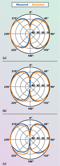
Fig. 6 Far-field radiation patterns of Antenna 2 in the y-z plane; (a) F=1.90 GHz, (b) F=2.20 GHz and (c) F=2.45 GHz. | 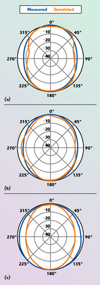
Fig. 7 Far-field radiation patterns of Antenna 2 in the x-y plane; (a) F=1.90 GHz, (b) F=2.20 GHz and (c) F=2.80 GHz. |

Fig. 8 Far-field radiation patterns of Antenna 4 in the y-z plane; (a) F=2.33 GHz, (b) F=3.65 GHz and (c) F=5.23 GHz. | 
Fig. 9 Far-field radiation patterns of Antenna 4 in the x-z plane; (a) F=2.33 GHz, (b) F=3.65 GHz and (c) F=5.23 GHz. |
These results can explain that all the operating frequencies have the same polarization plane and similar radiation patterns. It is noted that, for the frequencies within the impedance bandwidth of Antenna 4, approximately 2.9 GHz, the radiation patterns are found to be tilted by a small angle at the higher frequencies, and the maximum radiation direction is no longer in the broadside direction of the antenna. One reason is a mismatch between the microstrip-feed line and the isosceles triangular slot. The more important causes are the non-uniform phase distribution of the field in the isosceles triangular slot and some undesired higher order modes of the printed slot antenna that are also excited. These effects could cause some distortions in the resultant radiation patterns.

Table 6 shows the peak gain of Antennas 2 and 4 over the entire band by showing its values at particular frequencies. It is clear that two designs have similar properties in the entire band. They achieve good power gain, with impedance bandwidth ranges from 44.1 to 76.7 percent, which are required in wireless local area network communication applications. Also, Figure 10 shows the peak gain of Antennas 2 and 4, where the gain variation of Antenna 4 is observed to be less than 1.8 dB and the peak antenna gain of Antenna 4 is about 5.9 dBi.

Fig. 10 Measured peak gain of Antenna 2 (a) and Antenna 4 (b)
Conclusion
A microstrip-line-fed, printed isosceles triangular slot antenna, with a small rectangular slot for broadband operation has been implemented. Several design examples have been successfully demonstrated. Experimental results show that the impedance bandwidth of a printed isosceles triangular slot antenna can significantly be improved by selecting the proper dimensions of the small rectangular slot and choosing the optimal flare angle a of the printed isosceles triangular slot. The results of this study show that the impedance bandwidth of the proposed antenna can be approximately 2.9 GHz (2.33 to 5.23 GHz), which is approximately 4.6 times that of a conventional microstrip-line-fed, printed isosceles triangular slot antenna (16.6 percent). In this proposed design, an impedance bandwidth of approximately 76.7 percent (VSWR £ 2) has been obtained. This type of antenna will find applications in future wireless communications, such as IEEE802.11 a/b/g, PHS, PCS, GSM, Bluetooth, UMTS, PACS, UWB and HIPERLAN/1/2.
Acknowledgment
The financial support of this study by the National Science Council, Taiwan, Republic of China, under contact number NSC92-2213-E-218-038, is gratefully acknowledged.
References
1. K.L. Wong, Compact and Broadband Microstrip Antennas, John Wiley & Sons Inc., New York, NY, 2002.
2. M. Kahrizi, T.K. Sarkar and Z.A. Maricevic, “Analysis of a Wide Radiating Slot in the Ground Plane of a Microstrip-line,” IEEE Transactions on Microwave Theory and Techniques, Vol. 41, No. 1, January 1993, pp. 29–37.
3. S.M. Shum, K.F. Tong, X. Zhang and K.M. Luk, “FDTD Modeling of Microstrip-line-fed Wide-slot antenna,” Microwave Optical Technology Letters, 1995, pp. 118–120.
4. A.Z. Elsherbeni, A.A. Eldek, B.N. Baker, C.E. Smith and K.F. Lee, “Wideband Coplanar Patch-slot Antennas for Radar Application,” IEEE International Symposium on Antennas and Propagation Digest, San Antonio, TX, June 2002, pp. 436–439.
5. J.Y. Sze and K.L. Wong, “Bandwidth Enhancement of a Microstrip-line-fed Printed Wide-slot Antenna,” IEEE Transactions on Antennas and Propagation. Vol. 49, 2001, pp. 1020–1024.
6. M.K. Kim, K. Kim, Y.H. Suh and I. Park, “A T-shaped Microstrip-line-fed Wide Slot Antenna,” IEEE International Symposium on Antennas and Propagation Digest, Vol. 3, 2000, pp. 1500–1503.
7. W.S. Chen, C.C. Hung and K.L. Wong, “A Novel Microstrip-line-fed Printed Semicircular Slot Antenna for Broadband Operation,” Microwave Optical Technology Letters, Vol. 26, No. 4, August 2000, pp. 237–239.
8. M.Yamazaki, E.T. Rahardjo and M. Haneishi, “Construction of a Slot Coupled Planar Antenna for Dual Polarization,” Electronics Letters, Vol. 30, 1994, pp. 1814–1815.
9. J.R. Sanford and A. Tengs, “A Two Substrate Dual-polarized Aperture Coupled Patch,” IEEE International Symposium on Antennas and Propagation Digest, 1996, pp. 1544–1547.
10. B. Lindmark, “A Novel Dual-polarized Aperture Coupled Patch Element with a Single Layer Feed Network and High Isolation,” IEEE International Symposium on Antennas and Propagation Digest, 1997, pp. 2190–2193.
11. B. Lindmark, S. Lundgren, J.R. Sanford and C. Beckman, “Dual-polarized Array for Signal-processing Applications in Wireless Communications,” IEEE Transactions on Antennas and Propagation, Vol. 46, 1998, pp. 758–763.
12. S.D. Targonski, R.B. Waterhouse and D.M. Pozar, “Design of Wideband Aperture-stacked Patch Microstrip Antennas,” IEEE Transactions on Antennas and Propagation, Vol. 46, 1998, pp. 1245–1251.
13. R. Janaswamy and D.H. Schaubert, “Characteristic Impedance of a Wide Slotline on Low Permittivity Substrates,” IEEE Transactions on Microwave Theory and Techniques, Vol. 34, No. 8, August 1986.