
 When testing an antenna, the test engineer must typically measure a number of parameters such as the radiation pattern, gain, impedance, or polarization characteristics. One of the techniques used to measure antenna patterns is the far-field range where an antenna under test (AUT) is placed in the far-field of a transmit range antenna. A second technique is the near-field range where the AUT is placed in the near-field and then the data is mathematically transformed to the far-field. Radar Cross-Section (RCS) measurements are used to measure the angle-dependent echo characteristics of radar targets. Depending on the antenna and the application, a near-field, far-field or RCS range will be the preferred technique to properly determine the amplitude and/or phase characteristics of an AUT.
An instrument designed to address these techniques is the new PNA-X Measurement Receiver from Agilent Technologies, which offers the speed, accuracy, sensitivity and flexibility required for near-field, far-field or RCS antenna measurements. With a data acquisition speed of 400,000 data points per second simultaneously on each of five receiver channels, it sets the standard for antenna test applications.
Antenna-range Measurement
A typical antenna-range measurement system can be divided into two separate parts: the transmit site and the receive site. The transmit site consists of the microwave transmit source, optional amplifiers, transmit antenna and communications link to the receive site. The receive site consists of the AUT, a reference antenna, receiver, LO source, RF downconverter, positioner and a PC controller.
On a traditional far-field antenna range, the transmit and receive antennas are typically separated by a distance sufficient to simulate the intended operating environment. The source antenna illuminates the AUT at a distance far enough away to create a near-planar phase front over the AUT’s electrical aperture. Far-field measurements can be performed on indoor and outdoor ranges. Indoor measurements are typically made in an anechoic chamber specifically designed to reduce reflections off the walls, floor and ceiling.
Measurement of an object’s RCS is performed at a radar reflectivity range or scattering range. The first type of range is outdoors where the object is positioned on a specially shaped low-RCS pylon some distance down range from the transmitters. As with far-field antenna measurements, an anechoic chamber is also commonly used for indoor RCS measurements. Here the object is placed on a rotating pillar in the center of the chamber. The walls, floors and ceiling are covered by radar absorbing material to prevent corruption of the measurement due to reflections.
Fast, Accurate Measurement
The PNA-X Measurement Receiver has the features and performance to make such measurements accurately and efficiently. An optional Fast-CW mode enables a 500 million point data buffer, which allows users to stream almost infinite amounts of data directly to the network. It also provides dynamic range of 134 dB at 10 Hz IFBW, with up to five channels/unit.
The instrument includes an optional, built-in 26.5 GHz LO source with +10 dBm of output power, which can be used as a signal source for remote mixers or frequency converters. It is also compatible with the manufacturer’s MXG/PSG signal sources, existing 85309A distributed frequency converter and 85320A/B mixers. Combining the receiver with an MXG source typically results in a system speed improvement that is 10 times faster than existing systems.
The PNA-X Measurement Receiver is built on the Agilent PNA-X network analyzer technology platform and therefore provides a number of key benefits for antenna test applications, including:
High Sensitivity
The measurement receiver provides fast throughput and a low noise floor. Engineers can select from a minimum of 29 different IF bandwidths, optimizing sensitivity versus measurement speed to fit a particular measurement and application requirement.
Increased Speed
COM/DCOM features help the PNA-X realize extremely fast data transfer rates, while LAN connectivity through a built-in 10/100 Mbps LAN interface enables the PC to be located at a distance from the test equipment. These features enable remote testing as well as reduced test time.
Flexibility and Accuracy
For maximum flexibility, the instrument provides up to five simultaneous test receivers (A, B, C, D and R), with each receiver capable of measuring up to 400,000 points of data. It supports synchronization with external signal generators to further enhance performance and improve measurement accuracy.
Security
For secure environments, the PNA-X features a removable hard drive to completely ensure the security of the data it acquires.
Antenna Applications
With its array of features and benefits, the PNA-X can be easily integrated into near-field, far-field and RCS measurement systems, as is illustrated in Figures 1 and 2.

Figure 1 Typical compact range configuration.
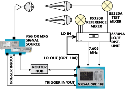
Figure 2 Typical remote mixing configuration.
For far-field or large near-field antenna applications, the PNA-X Measurement Receiver-based system incorporates the manufacturer’s 85320A/B broadband external mixers and 85309A distributed frequency converter. Its optional, built-in 26.5 GHz synthesized source is used as the LO source for the 85309A LO/IF distribution unit.
The instrument’s ability to obtain more than 400,000 points of data per second makes it ideal for far-field antenna range applications. Extremely fast data processing is particularly useful in applications where ranges include active array antennas and data acquisition is therefore quite intensive. With faster data acquisition speeds, the IF bandwidth can be narrowed, significantly improving measurement sensitivity without increasing total measurement times.
High-power pulses are often used in RCS measurements to overcome losses due to low device reflection and two-way transmission path loss. Receiver gating may therefore be required in a PNA-X RCS configuration to avoid overloading the receiver during the transmission of the pulsed-RF signal (see Figure 3).

Figure 3 Typical RCS measurement configuration.
With the source and receiver integrated into the same instrument, with a choice of frequency ranges, a PNA-X RCS configuration is cost effective. Extremely long alias-free down-range resolution for RCS measurements is achievable through the 100,000 data points per measurement trace. In addition, the removable hard drive in the PNA-X complies with data security requirements.
Conclusion
Given today’s increasingly complex antenna architectures and technologies, quickly and accurately characterizing an antenna and ensuring that it meets specification can be challenging. The PNA-X Measurement Receiver offers the speed, accuracy, measurement sensitivity and flexibility required to accomplish this task. All of these capabilities make the receiver well suited for near-field, far-field and RCS antenna measurement applications, making it an essential tool for today’s antenna test engineer.
Agilent Technologies,
+31 (0) 20 547 2111,
contactcenter_benelux@agilent.com,
www.agilent.com.
RS No. 300