
Ultra-wideband (UWB) wireless is a rapidly growing technology that promises to revolutionize low power, short-range wireless applications. UWB has quickly emerged as the leading technology for Wireless Universal Serial Bus (W-USB). UWB radios differ from conventional narrowband radios and have a variety of specialized test demands. Enormous signal bandwidths, short duration pulses and transmit Power Spectral Densities (PSD) near the thermal noise floor make UWB testing difficult. Fortunately, the current generation of test equipment has the bandwidth, sensitivity and software needed for testing UWB waveforms. In this article, the concepts behind UWB technology, its unique hardware and software architectures, and some of the associated test issues are explained.
Ultra-wideband technology is quickly gaining acceptance as a useful wireless technology. UWB offers bandwidth and the accompanying throughput needed for many of today’s high data rate applications such as wireless video, PC connectivity and high data rate mobile devices.
While UWB signals simply cannot have their own spectrum in today’s crowded RF environment, it is possible to transmit UWB signals over a spectrum dedicated to other uses as long as the power levels are sufficiently low, just above the noise floor. The combination of low power levels and the resultant low range minimizes expected interference levels. The very wide bandwidth of UWB signals gives immunity to single narrowband interference sources. Scenarios using multiple narrowband interferers may reduce UWB throughput, but pre-release testing can mitigate this concern.
In the same manner, destructive multi-path phenomena that can greatly affect a narrowband signal transmission have a much smaller effect on a UWB signal, since any cancellation notch caused by multi-path will affect only a narrow band of frequencies. UWB’s high data rate, multi-path immunity and robustness to interference make it an attractive wireless technology for today’s bandwidth-hungry computer peripherals.
What is UWB?

Figure 1 UWB signal definition.
UWB communications signals initially went by other names, such as impulse radio, baseband communications, carrier-free transmission and impulse modulation. It was in the 1980s that the term UWB was first applied to this fascinating class of signals, which had grown vastly in bandwidth. Many UWB design approaches differed substantially from conventional wireless links by not employing the ubiquitous super heterodyne frequency conversion architecture. Although modern super heterodyne radio architectures can now produce signals of comparable bandwidths and pulse widths, the simplicity of baseband or homodyne architectures are still attractive. Since UWB signals have a wide variety of modulation formats and radio architecture, the US Federal Communications Commission (FCC) spectral regulatory agency has selected a definition of UWB based on fractional bandwidth, or equivalent bandwidth. The US FCC defined a UWB signal as any signal with a bandwidth at the 10 dB attenuation point greater than 20 percent of the modulation frequency or an equivalent bandwidth greater than 500 MHz, as illustrated in Figure 1.
How UWB Works
There are several different approaches to generating ultra-wideband signals, including three popular methods: Time Hop UWB (TH-UWB), Direct Sequence UWB (DS-UWB) and Multi-band Orthogonal Frequency Division Multiplexing UWB (MB-OFDM).
TH-UWB

Figure 2 TH-UWB signal generation.
Time hop UWB signals are composed of a series of very short impulses at pseudo-random intervals. The TH-UWB signal begins by taking the data and repeating each bit multiple times. This repetition block coding adds signal redundancy and spectral diversity, increasing the signal’s immunity to multi-path variation and interference. Next, TH-UWB assigns each coded bit a pseudo-random value for signal spreading. The TH-UWB Pulse-position Modulation (PPM) technique then uses the pseudo-random transmission spreading code to select a time slot proportional to the assigned pseudo-random value and generates a pulse. This technique modulates the position of each pulse, generating a pseudo-random stream of pulses. Of course, there are many variations possible, but this is the basic process used for time hopping UWB signals. Pulse shaping and amplifying is the last step in preparation for transmission. The TH-UWB generation with PPM is a simple process of coding, spreading, modulating and shaping the short impulses that make up the signal. TH-UWB creates the signal at baseband and does not need frequency up-conversion, as shown in Figure 2.
Pulse Shaping

Figure 3 The pulsed signal bandwidth is inversely related to the pulse width in the time domain.
Pulse shaping is important because it affects the spectral properties of the UWB modulation (see Figure 3). The frequency-domain spectral shape corresponds to the time-domain impulse shape. For example, the theoretical Dirac impulse, or infinitely narrow pulse width in the time domain, creates an infinitely wide spectral response in the frequency domain. Carefully changing the impulse shape can control the power spectral density of the TH-UWB signal.
Pulse shaping is also important because it can affect the Inter-symbol Interference (ISI) and multi-path characteristics of a TH-UWB signal. Unlike many traditional narrowband digital modulations that use raised cosine filtering and controlled symbol timing to avoid ISI, UWB signals often favor Gaussian pulse shapes, which retain their shape better when confronted with dispersive channel effects. The Gaussian pulse shape does introduce some ISI, but UWB signals have plenty of bandwidth, so it is possible to make timing adjustments to minimize inter-symbol interference.
Baseband UWB Impulse Radio
It is important to note that the TH-UWB hardware can create almost the entire signal in baseband. Baseband generation of the transmitted signal eliminates the need for many conventional super heterodyne components, such as up and down converters, IF filters, amplifiers, mixers and LO sources. This makes Impulse Radio UWB designs significantly less complex and costly. It also allows extensive applications of the many benefits of Digital Signal Processing (DSP).
DS-UWB
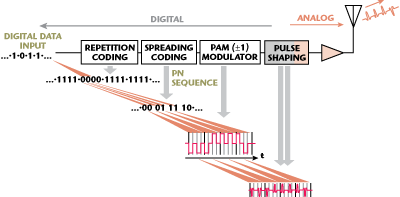
Figure 4 DS-UWB signal generation.
Direct Sequence UWB (DS-UWB) is another modulation approach used to create ultra-wideband signals. As shown in Figure 4, DS-UWB pulse amplitude modulation signal generation is similar to TH-UWB. A key difference is in the pulse modulator that inverts the phase of the pulse. DS-UWB employs techniques similar to Direct Sequence Spread Spectrum (DSSS). These techniques spread the impulse radio spectrum over ultra-wide bandwidths. The repetition block coder encodes bits and provides a positive or negative value for each. This increases redundancy and improves spectral diversity for robust transmission characteristics.
Next, the Pseudo Noise (PN) transmission channel encoder assigns a pseudorandom value to each redundant bit. The output is a spread sequence of positive and negative values. The Pulse Amplitude Modulator (PAM) then generates positive and negative pulses. These pulses are subsequently pulse shaped and amplified for transmission.
Though this process is similar to the DSSS BPSK modulation commonly used with continuous waveforms, pulse modulation, or inversion, is accomplished digitally prior to pulse generation and shaping. DS-UWB like TH-UWB can also use the simpler baseband, zero-IF, or homodyne architectures for signal generation and reception, allowing many hardware architectural simplifications, compared to a super-heterodyne radio.
MB-OFDM
Generating UWB signals with MB-OFDM is another important approach. Since the US FCC regulations stipulate only bandwidth and power spectral density requirements, they allow conventional modulations, like orthogonal frequency division multiplexing (OFDM), as long as the spectrum has sufficient bandwidth. Multi-band (MB) OFDM uses a frequency hopping technique. This allows further spreading of the conventional OFDM signal and makes it UWB for regulatory purposes. The problem is that current low cost OFDM modulators can only achieve a little over 500 MHz of modulated signal bandwidth. Using a simple frequency hop pattern over three bands in conjunction with a conventional OFDM signal, designers can create over 1.5 GHz of bandwidth.
OFDM signals have outstanding multi-path rejection. Since OFDM is composed of many signal carrier modulations closely spaced together yet still remaining orthogonal, each signal carrier can have a much slower data rate than the combined set of signals. Simultaneously sending many parallel, individually slower carriers allows corresponding longer symbol times when compared to a single carrier transmission. Even so, the parallel transmission preserves, and even enhances, the data rate. This greatly reduces Inter-symbol Interference (ISI) caused by time spreading from multi-path. OFDM thus provides very robust performance when channel characteristics are poor. In particular, MB-OFDM is an attractive modulation for indoor environments, where poor transmission channel conditions are prevalent.
The WiMedia Signal
The WiMedia® Alliance has selected an MB-OFDM signal as its high-speed multi-media UWB data link standard. The WiMedia signal is composed of an OFDM modulation with 128 carriers, using either Quadrature Phase Shift Keying (QPSK) or Dual Carrier Modulation (DCM) on each carrier. This modulation format allows at least eight data rates ranging up to 480 Mb/s.

Figure 5 MB-OFDM UWB spectrum bands.
The WiMedia OFDM modulation is frequency hopped over a band group composed of 528 MHz wide bands, as shown in Figure 5. A Time Frequency Code (TFC) then controls the hopping of the OFDM signal across the band group. Relative to most Frequency Hop Spread Spectrum (FHSS) signals, the MB-OFDM WiMedia signal hops slowly, with an uncomplicated hopping pattern, sending many bits during each hop.
The US FCC was the first to open up radio spectrum for UWB use. Other countries have quickly followed the US FCC initiative; however, not all bands are available worldwide for UWB applications. Some countries require or will require Detect And Avoid (DAA) schemes where transceivers listen to the band for other signals before transmitting to help mitigate interference. WiMedia signals that rely on complex protocols, like many UWB signals, can be difficult to test with older traditional instruments. The unusual nature of the UWB signal combined with radically different hardware architectures that often lack traditional test-points present unique challenges for the engineer.
A Challenging Test Problem
UWB signal requirements present broadband amplitude and phase flatness challenges. Test signal generators and measurement instruments can distort UWB signals due to spectral amplitude and phase flatness issues. These flatness issues create pulse distortions, which affects the spectral properties of UWB signals. The normal way to minimize flatness issues is to choose test equipment with a significantly wider bandwidth than the signal under test. However, for UWB signals, this is not always possible. Another problem encountered when testing UWB signals is the limited measurement bandwidth options available. Even simple power spectral density measurements can be difficult, as regulations require a 50 MHz resolution bandwidth (RBW) few spectrum analyzers support. Add to these challenges Time Frequency Codes (TFC) that spread and hop the UWB signal, and device test can be a major challenge without the right test equipment.
How to Test UWB Devices
There are many wireless test instruments on the market, but only a few are suitable for UWB devices. To follow are some common problems and the test solutions that are available for UWB applications.
Efficient WiMedia Signal Simulation
UWB signals, as the name implies, are very wide band. This makes signal generation a challenge, particularly when the signal generator needs to be flexible. Most common laboratory signal generators are capable of generating only a few tens or hundreds of megahertz (MHz) of bandwidth, which is far short of the one and a half gigahertz of bandwidth necessary for most UWB signals.
Different UWB modulation types require different signal generation approaches. Signals like TH-UWB and DS-UWB can be generated entirely at baseband and require many gigahertz of baseband bandwidth. Other signals like MB-OFDM are more typically upconverted to the appropriate RF band. Upconversion methods require less baseband bandwidth from the signal generator, but add the complexity of an external up-converter or modulator. A simple solution is to use the UWB’s own system software to generate test signals, but this approach is not without issues. The primary problem is that, early in the development cycle, the design may not be working properly, leading to potentially serious test issues. In addition, the radio system under development usually lacks the ability to add impairments and can be cumbersome to manipulate for test purposes.

Figure 6 A modern AWG supports direct baseband and external I-Q modulator/upconverter UWB signal generation approaches.
A preferred approach is to use a known good signal generator with a software package that can reliably synthesize both general purpose and standards based signals, with or without impairments. This eliminates uncertainty with the test signal and provides an easy-to-use human interface, accelerating the design and debug process. A modern Arbitrary Waveform Generator (AWG) can directly generate RF for BG1 and BG2 of the WiMedia MB-OFDM signals. It can also provide direct baseband outputs or I-Q outputs for up-conversion needs, as illustrated in Figure 6. These outputs will be available in differential form to allow a direct interface with popular balanced amplifier and mixer components and so offer the improved noise immunity of common mode rejection.
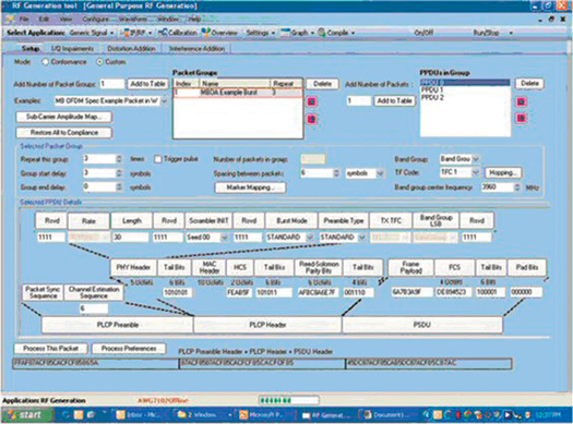
Figure 7 The RFX software package can synthesize WiMedia packet waveforms from the packet group level.
Several general-purpose signal-synthesizing software tools work with current AWGs. A software tool such as that illustrated in Figure 7 is useful for general-purpose signal creation as well as signal creation for specific standards, including WiMedia, allowing for spectral environment simulation, functional test and conformance test of WiMedia devices. Specifically, a signal-synthesizing tool, in combination with an AWG, will allow engineers to create, modify and control protocol elements for functional test. It will also allow creation of a wide variety of signal impairments in the form of gated noise, distortion and I-Q impairments. On channel and adjacent channel interference from nearby UWB technology devices can be emulated. Development risks can be lowered and more robust radios created by using test signals that are impaired in known ways and receiver margin testing can be performed.
Efficient Interference Testing
Experts have cited UWB interference susceptibility as a significant challenge. The large bandwidth a UWB signal covers naturally invites a wide range of potential narrowband interference sources. Both in-band and nearby out-of-band interference sources can cause problems. UWB designs often lack the selectivity of sharp IF filters, necessitating even wider test bandwidths. Optimizing interference performance can be a particularly challenging issue as UWB links rarely have interference issues with just a single narrowband interferer. This requires engineers to create complex spectral test environments to completely characterize designs. Simulating harsh interference-filled spectral environments that encompass large bandwidths can be expensive. The conventional approach of summing multiple signal sources together in order to generate a realistic interference environment typically requires a significant investment in signal sources.
A better approach to creating interference test signals is to use an AWG, with ultra-wide bandwidth, and a signal-synthesizing program, to create an entire spectral environment from a single source. There are two ways to make this happen. The first is to generate an array of narrowband spectral interferers, sum this array with a desired UWB signal, and play it all back with an AWG. The second approach is to record an actual spectral environment with a wideband device such as a high-speed oscilloscope. Once captured, an engineer can play back the off-the-air signal with an AWG, making it easy to judge the effectiveness of design improvements using consistent, repeatable, real-world interference.
A single ultra-wideband AWG, the right software and a high-speed oscilloscope can replace many expensive independent signal generators, and is a much more cost-effective and flexible solution to evaluate UWB interference susceptibility with other UWB devices.
UWB Spectrum Measurements
UWB spectral measurements present some unusual challenges for development and test engineers. Highly integrated UWB devices often allow spectral measurements only from radiated signals. Internal test point connections may not exist or may not reflect the attenuation characteristics of an ultra-broadband antenna. Adding to these issues, the transmit signal is likely to be near the noise floor, requiring a very sensitive spectrum analyzer or external preamplifier.
Regulatory requirements for UWB signals dictate a 50 MHz resolution bandwidth for spectral power measurements. UWB signals cover large swaths of spectrum and some of the licensed channels contained in this spectrum can be up to 50 MHz wide. This requires RBWs of 50 MHz to accurately assess the potential for interference. This requirement eliminates many popular spectrum analyzers as only a few have internal bandwidths this wide.
Oscilloscopes usually lack the dynamic range of the typical spectrum analyzer, making setup for some measurements more cumbersome. However, a few high-speed oscilloscopes have the needed sensitivity and have internal Fast Fourier Transform (FFT) capability. This allows the generation of spectral emission plots from the time-domain signal capture. Add a spectral mask measurement to the high-speed oscilloscope and you have a complete package for WiMedia UWB signals. In the case of WiMedia, it is important that the oscilloscopes’ UWB analysis software automatically identifies the Time Frequency Code (TFC) of the signal and selects the correct spectral mask to apply. The software can then determine if the signal passes or fails the mask, and measure the total integrated channel power. For diagnostic purposes, it is important that the software measure mask hits independently for each band in, and outside of, a band group. Finally, an Adjacent Channel Power Ratio (ACPR) test will give developers insight into distortion issues. Once the UWB spectrum is compliant with regulations, the next measurement concern is usually optimizing modulation performance.
UWB Modulation Measurements
WiMedia’s MB-OFDM UWB modulation is complex and presents several challenges when characterizing performance. Unlike many narrowband modulations that rely on outstanding component performance over narrow frequency ranges, ultra-wideband component characteristics often produce distortions. For example, amplitude flatness, group delay variations and frequency hopping glitches can all degrade valuable link performance. Detecting these and other problems within a multi-band signal requires capabilities far beyond simply capturing the time-domain waveform.

Figure 8 UWB analysis software automatically identifies the TFC and measures the constellation of a signal OFDM carrier.
Another issue is that developers need to identify the TFC for the WiMedia signal under test. This is difficult if the operational mode of the device under test is unknown. An oscilloscope with strong UWB analysis capabilities will be able to take a captured waveform and identify the TFC, hopping sequence and data rate automatically for all WiMedia band groups, simplifying testing for compliance testing (see Figure 8).
The next task is to run modulation quality checks, which should include Error Vector Magnitude (EVM), Peak EVM, data rate, center frequency, number of data symbols and Common Phase Error (CPE). The modulation quality values are essential to understanding signal accuracy and, ultimately, can affect device throughput in service and device margin in manufacturing.
The UWB EVM computation is more complex than traditional continuous wave measurements. UWB EVM includes an initial Channel Estimation (CE) using the CE symbols to provide a phase and timing estimation. As a result, EVM measurement software needs to be able to provide CE corrections to the pilot tones. In addition, the specific type of correction needs to be selectable by the user. This makes EVM measurements more complex than one might expect, requiring greater capability from the measurement software.
Conclusion
UWB technology offers many benefits. High-speed connections, interference protection and simple hardware architectures are a few of the characteristics that are propelling the rapid growth of UWB devices. TH-UWB, DS-UWB and MB-OFDM techniques are reshaping short-range high-speed wireless data links. The measurement challenges of UWB are often very demanding; bandwidth requirements alone eliminate many test instruments. However, it is now easier to design and produce UWB products because wideband AWG signal generators are now available. These wideband AWGs are capable of producing UWB signals, additive impairments and broadband interference test spectrums.
Software driven waveform synthesis tools are available to generate waveforms for playback on AWGs. These tools enable easy programming of complex waveforms. Signals like WiMedia’s MB-OFDM can be quickly assembled from simple choices at the protocol bit level. Some waveform synthesis tools can also control oscilloscopes for unmatched “off-air” signal recording and playback. Real-time oscilloscopes complement the AWG signal sources. Some of these oscilloscopes offer not only the bandwidth to capture UWB signals, but also a unique set of UWB modulation measurements for popular WiMedia signals. The UWB analysis software provides unmatched insight into MB-OFDM signal performance. Testing UWB devices takes state-of-the-art measurement instruments. Fortunately, advanced testing of UWB signals is now easier than ever with the right UWB tools.
Darren McCarthy earned his BSEE degree from Northwestern University, Evanston, IL. He is a technical marketing manager for RF Test at Tektronix and has worked extensively in various test and measurement positions for the last 18 years, including R&D engineer, R&D management, product planning and business development. During his career, he has also represented the US on several IEC Technical Committees for international EMC standards.