
Class-E power amplifiers (PA) offer high efficiency. However, with broadband load networks, their harmonic performance degrades. This article introduces a practical implementation to achieve high harmonic suppression in a broadband class-E amplifier design by combining a parallel-circuit load network with a reactance compensation technique. A three-stage power amplifier is used to provide high gain and output power as required for two-way radio applications. The final PA stage uses a broadband class-E design, which combines a parallel-circuit load network with a reactance compensation technique. A novel series LxCx, with a high-Q roll-off harmonic filter (elliptical type), provides high harmonic suppression while maintaining the class-E switching mode over a broad frequency band. An efficiency of 70 percent and a second-harmonic suppression of –73 dBc across a wide bandwidth (135 to 175 MHz), at an operating power of 6.5 W, are demonstrated. Up to now, these harmonic and efficiency results are the highest obtained over a broad VHF frequency band, with a low supply voltage of 7.2 V.
Modern portable two-way radios are required to operate over a large number of channels for a long period of time from a small size battery. This means that an effective battery life solution is necessary. In radio transmitters, the PA is generally the main consumer of battery dc power. Therefore, the best way of improving battery life is to increase the PA efficiency.
Class-E PA circuits are suitable for high efficiency amplification at radio frequency and microwave ranges. The concept of class-E with shunt capacitance was introduced by Sokal.1 Grebennikov proposed a broadband class-E design,2 combining a parallel-circuit load network with reactance compensation, which is very suitable for practical two-way radio applications. The use of a low dc-feed inductance, a higher load resistance, a larger shunt capacitance and a higher maximum operating frequency topology are attractive solutions that have some advantages over class-E with only a shunt capacitance.2,3 However, due to the inherent asymmetrical input drive of class-E, significant harmonic content is generated in the output voltage and current.4,7
The conventional design of a high-efficiency switched-mode tuned PA requires a high-QL factor to satisfy the necessary harmonic impedance conditions at the output device terminal.5 In this article, a series LxCx, with an elliptical harmonic filter, provides high harmonic suppression while maintaining the broadband switching mode of class-E. A high harmonic suppression (more than –73 dBc) and efficiency (70 percent) are demonstrated experimentally over a broad frequency range, from 135 to 175 MHz. In a comparable work,6 Mury demonstrated a second-harmonic suppression of 47 dBc for a power of 22 dBm.
Broadband Class-E PA with Series LC and High-Q Roll-off Harmonic Filter for High Harmonic Suppression

A three-stage amplifier chain was chosen to achieve high gain and high output power. The first stage (ADA4743-HBT device)9 and second stage (RD01MUS1-LDMOS device)10 operate in class-AB. A direct matching technique was used for the output match of the second stage and input match of the final stage. The optimum load impedance of the second stage and optimum source impedance of the final stage PA were obtained from simulation and correlated with load-pull measurements. A 7.2 V supply voltage was used for the second and third stages and 5 V was applied to the first stage. The RD07MVS1-LDMOS device11 was used for the broadband class-E power stage design that combines the parallel-circuit load network with a reactance compensation technique.
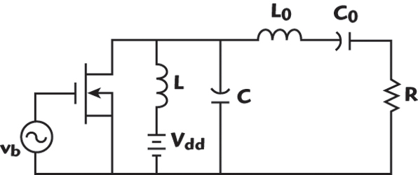
The parallel-circuit class-E PA provides the condition that high currents and high voltages do not occur simultaneously. This condition minimizes the power dissipation within the device. The load network consists of a parallel inductance L, a parallel capacitance C, a series L0C0 resonant circuit tuned at the fundamental and a load R,3 as shown in Figure 1.
The shunt LC-circuit provides a constant load phase angle relative to the device output terminals.3 An additional low-pass matching section, transforming the impedance from load R to a 50 Ω termination, can be typically implemented to increase the harmonic suppression. Figure 2 shows a broadband (135 to 175 MHz) class-E parallel-circuit load network, combining a reactance compensation technique with an additional three-section matching network to deliver a power of 8 W, using a 7.2 V supply voltage.
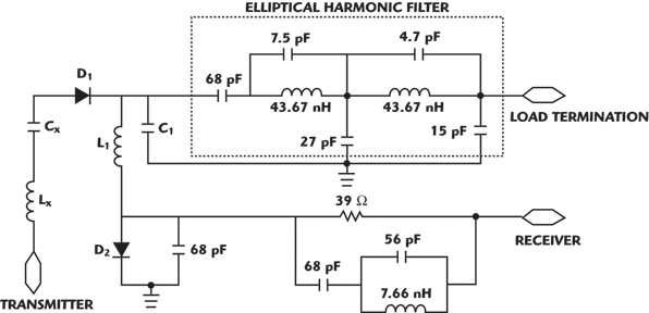
The harmonic suppression, in two-way radio applications, needs a typical 73 dBc reduction of the second harmonic at VHF and UHF frequencies and, typically, higher harmonics are not an issue. An additional high-Q roll-off harmonic filter is definitely required to provide high suppression of the second and other harmonic levels. A high-Q roll-off elliptical harmonic filter is chosen. However, in two-way radio applications, an RF switch is necessary between receiver and transmitter modes. Figure 3 shows an optimized elliptical harmonic filter and RF switch for the broadband frequency range of 135 to 175 MHz.

A pin diode switch (D1 and D2) is turned on by an external DC source and provides low impedance. L1 and C1 are tuned for adequate receiver isolation. With the cascade of an elliptical harmonic filter and RF switch, the class-E switching action for broadband frequency (135 to 175 MHz) was not fulfilled. The combination of the elliptical harmonic filter and RF switch section was built and the S-parameters of the two-port network were measured with an HP6788 network analyzer. The measured results showed that the real input impedance was approximately 46 Ω and the imaginary input impedance moved from inductance to capacitance with a high variation of 20 Ω across the broadband range, as shown in Figure 4. In the design, the transformation of the output impedance load network from R to 46 Ω load impedance is required.
A series LxCx compensation network is introduced to flatten the phase angle, as shown in Figure 5. The measured results showed that, with the series LxCx, the imaginary variation is minimized to 5 Ω across the bandwidth without affecting the real part. With the series LxCx, the imaginary impedance behaves as a capacitance across the bandwidth. This way, the three-section matching network can absorb the variation.

The measured passband insertion loss and harmonic attenuation of the elliptical harmonic filter and RF switch with series LxCx are shown in Figure 6. The insertion loss across the bandwidth is 1.2 dB and the second-harmonic attenuation is greater than 45 dB.
Implementation and Experimental Results Validation
A prototype board of the class-E final PA, using a parallel-circuit combining reactance compensation together with a series LxCx network, an elliptical harmonic filter and RF switch was designed and fabricated. The first- and second-stage PAs were built as well. The PCB (FR-4 material) has a dielectric ερ = 4.5 and thickness h = 14 mils. A heatsink is mounted at the bottom of the final PA in the PCB.

Since the insertion loss of the elliptical harmonic filter and RF switch is 1.2 dB across the bandwidth, the final PA must compensate the losses to deliver 6.5 W of power at the load termination. The final PA is delivering 8 W with a supply voltage of 7.2 V. A typical gate voltage of 1.8 to 1.9 V has been applied to the gate of the final PA. In order to provide sufficient RF input to the final PA with fast rise and fall times across the bandwidth, the gate voltage of the second-stage PA can be adjusted (a gate voltage of 2.1 to 2.4 V is applied).
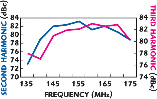
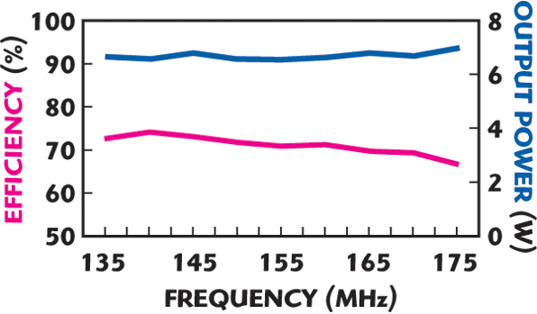
The measured second- and third-harmonic levels across the bandwidth are shown in Figure 7. The measured output power at the load termination and the final PA efficiency are shown in Figure 8. A final PA efficiency of 70 percent at an operating power of 6.5 W was demonstrated across the bandwidth (135 to 175 MHz) and a second-harmonic attenuation of –73 dBc was achieved across the bandwidth. A third-harmonic attenuation greater than –75 dBc was also achieved across the bandwidth.
Conclusion
High harmonic suppression while maintaining a class-E condition for a broad frequency range is achieved with a new type of load network circuitry. A broadband parallel-circuit class-E network, cascaded with a series LxCx and a high-Q roll-off elliptical harmonic filter was used for this implementation. The novel Lx Cx circuit compensates the large reactance variation of the elliptical harmonic filter, which enables class-E PA operation. An efficiency of 70 percent and a second-harmonic suppression of –73 dBc was measured across a wide bandwidth (135 to 175 MHz) with an operating power of 6.5 W. The efficiency and harmonic results are the highest reported so far at VHF frequencies with a 40 MHz bandwidth and a supply voltage of 7.2 V.
References
1. N.O. Sokal and A.D. Sokal, “Class-E: A New Class of High-efficiency Tuned Single-ended Switching Power Amplifiers,” IEEE Journal of Solid-state Circuits, Vol. 10, June 1975, pp. 168–176.
2. A.V. Grebennikov and H. Jaeger, “Class-E with Parallel Circuit: A New Challenge for High-efficiency RF and Microwave Power Amplifiers,” 2002 IEEE MTT-S International Microwave Symposium Digest, Vol. 3, pp. 1627–1630.
3. A. Grebennikov, RF and Microwave Power Amplifier Design, McGraw-Hill, New York, NY, 2004.
4. S.C. Wong, “Design of Symmetrical Class-E Power Amplifier for Very Low Harmonic-content Applications,” IEEE Transactions on Circuits and Systems-I: Regular Papers, Vol. I-52, August 2005, pp. 1684–1690.
5. A.V. Grebennikov, “Switched-mode RF and Microwave Parallel-circuit Class-E Power Amplifiers,” International Journal of RF and Microwave Computer-aided Engineering, Vol. 14, January/February 2004, pp. 21–35.
6. T. Mury and V.F. Fusco, “Inverse Class-E Amplifier with Transmission Line Harmonic Suppression,” IEEE Transactions on Circuits and Systems-I: Regular Papers, Vol. I-54, July 2007, pp. 1555–1561.
7. T. Mury and V.F. Fusco, “Transmission Line Matching Effects on the Performance of Shunt-C/Series-tuned and Series-L/Parallel-tuned Class-E Amplifiers,” 2005 Asia Pacific Microwave Conference Proceedings.
8. G.F. Engen and C.A. Hoer, “Thru-reflect-line: An Improved Technique for Calibrating the Dual Six Port Automatic Network Analyzer,” IEEE Transactions on Microwave Theory and Techniques, Vol. 27, No. 12, December 1979, pp. 987–993.
9. ADA-4743 Avago Technologies Pte., “Silicon Bipolar Darlington Amplifier” datasheet, 5989-3754EN, April 3, 2006.
10. RD01MUS1 Mitsubishi RF Power MOSFET datasheet; 10 Jan 2006.
11. RD07MVS1 Mitsubishi RF Power MOSFET datasheet; 10 Jan 2006.