
Recently, as wireless communications systems get smaller and lighter and are able to perform multi-functions, microwave components that have a small size and better performance are required. One of the methods used to meet these requirements is the low temperature co-fired ceramics (LTCC) process technology. The multi-layer technology using LTCC has become popular to meet the demands for compact size, high integrity and low cost.
Nonlinear circuits in wireless communications systems, such as mixers and amplifiers, usually generate unwanted frequency components in addition to the amplified desired signals. The unwanted frequency components are usually an image signal, harmonic components and intermodulation distortion components. These unwanted frequency components deteriorate the communications system performance.
Microwave filters are an essential component in wireless communication systems. Filters, with higher performance such as low insertion loss in the passband and high attenuation over a wide upper stop-band, are usually required. However, conventional bandpass filters that are composed of half- or quarter-wavelength resonators have inherently spurious passbands at 2f0 and 3f0, where f0 is the center frequency of the bandpass filter. Cascaded low pass and band-stop filters may be used to suppress the spurious passbands at the cost of extra insertion loss and size. Otherwise, slow-wave resonators and bandpass filters using slow-wave resonators are used to control spurious responses within a compact filter size.1–3 In wireless communication systems, the performance will be improved if filters with low insertion loss and wide upper stop-band can be used.
In this article, a quarter-wavelength resonator, loaded with spiral-shaped open-circuited stubs, is proposed. The proposed resonator is a slow-wave resonator, and so the efficient control of the distance between resonator patterns permits the control of the spurious response characteristics. Using the proposed resonator, a multi-layer, two-pole, bandpass filter was designed, fabricated and measured. LTCC process technology was used in the filter fabrication.
Resonator Loaded with Spiral-shaped Open-circuited Stubs
Figure 1 shows the proposed resonator and the evolution process that led to it. The resonator is composed of a main strip line and two spiral-shaped open-circuited stubs. The length of the spiral-shaped, open-circuited stubs determines the fundamental resonant frequency (f0) and the first spurious frequency (f1). The effect of the length of the open-circuited stubs on the resonance characteristics was calculated using EM simulation. The length of the main strip line is 1.0 mm, the dielectric constant of the LTCC substrate is 36 and the ground plane spacing is 0.864 mm. Figure 2 shows the simulated results. The ratio f1/f0 increases, as the length of the stub gets longer.

Fig. 1 Resonator loaded with spiralshaped open-circuited stubs; (a) resonator structure and (b) the evolution process.

Fig. 2 Resonant and first spurious frequency versus open-circuited stub length.
Filter Properties
Figure 3 shows the simple equivalent circuit that is used in the filter design and the top view of a multi-layer filter layout. This filter schematic has a feedback capacitor between the input and output ports and provides two finite transmission zeros on each side of the filter passband.4 In the filter layout shown, the short-circuited stubs are equivalent to a shunt inductor and operate as a K-inverter.5 The value of the K-inverter can be adjusted by changing the length and width of the short-circuited stubs. Because the total pattern of the filter must be embedded in a fixed space, in this case, the value of the K-inverter can be adjusted only by changing the width of the short-circuited stubs.

Fig. 3 Equivalent circuit of the proposed filter (a) and the top view of the filter layout (b).
LTCC Filter Implementation
Using the LTCC process technology, a 5.25 GHz, multi-layer, bandpass filter was fabricated for orthogonal frequency-division multiplexing (OFDM) wireless LAN communications. After co-firing, the dielectric constant and loss tangent of LTCC substrates are 36 and 0.002, respectively. The conductivity of the metal is 5.8 × 10⁷ S/m. The height of the unit green sheet is 0.036 mm; the total height is approximately 1.08 mm.
Figure 4 shows a three-dimensional view of the final filter layout. There are three important conductor pattern layers that are embedded in the strip-line structure. When the filter schematic was converted into a three-dimensional structure, no via-hole was used. The short-circuited stubs are grounded by connecting them to the side ground walls. By not using via-holes, several advantages are gained, including easy and simple fabrication, reduction of fabrication error and elimination of the problem originated from via-holes. Figure 5 shows a photograph of the fabricated LTCC bandpass filter. Its size is 2.0 × 1.2 × 1.1 mm.

Fig. 4 Three-dimensional view of the filter layout.

Fig. 5 Photograph of the fabricated LTCC filter.
Experimental Results
The fabricated filter characteristics were measured using a vector network analyzer (Agilent 8510C) and a test fixture designed for filter measurements (see Table 1). Since thousands of filter samples per process pass were manufactured, variables were assigned to each pattern layer parameter in order to examine the overall filter characteristics accordingly and the variation in filter characteristics were observed. In the case of the short-circuited stub that behaves as a K-inverter, as the stub is made wider, the value of the K-inverter is higher and the passband is wider. From the feedback capacitor, two transmission zeros on both sides of the passband are created and these transmission zeros are nearer to the passband as the length of the feedback capacitor is increased.
Figure 6 shows the filter’s measured S-parameters in the passband and harmonic bands. The filter, made with the proposed resonators, has a wide upper stop-band and the attenuation values are 30 dB at 2f0 and 20 dB at 3f0. The insertion losses of the fabricated filters are very low, less than 1.5 dB.
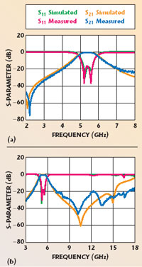
Fig. 6 Simulated and measured S-parameters of the passband filter; (a) passband and (b) spurious.
Conclusion
In this article, a resonator, loaded with spiral-shaped open-circuited stubs, and a well-known filter schematic having two finite transmission zeros, was proposed. A new, multi-layer LTCC bandpass filter was designed and fabricated using the proposed resonator. The filter is composed of the resonators and a K-inverter utilizing two short-circuited stubs. By using the advantages of size reduction and the ability to control the spurious response of the proposed resonator, it is possible to design compact bandpass filters with a wide upper stop-band. Since the structure has no via-hole, the fabrication process is very simple and easy, and the errors arising from the via-hole process can be suppressed.
References
1. M. Makimoto and S. Yamashita, “Bandpass Filters Using Parallel Coupled Strip-line Stepped Impedance Resonators,” IEEE Transactions on Microwave Theory and Techniques, Vol. 28, No. 12, December 1980, pp. 1413–1417.
2. J.S. Hong and M.J. Lancaster, “End-coupled Microstrip Slow-wave Resonator Filters,” ElectronicLetters, Vol. 32, No. 16, 1996, pp. 1494–1496.
3. J.S. Hong and M.J. Lancaster, “Microstrip Slow-wave Resonator Filters,” IEEE International Microwave Symposium Digest, 1997, pp. 713–716.
4. L.K. Yeung and K.L. Wu, “A Compact Second-order LTCC Bandpass Filter with Two Finite Transmission Zeros,” IEEE Transactions on Microwave Theory and Techniques, Vol. 51, No. 2, February 2003, pp. 337–341.
5. J.R. Lee, J.H. Cho and S.W. Yun, “New Compact Bandpass Filter Using Microstrip l/4 Resonators with Open Stub Inverter,” IEEE Microwave and Guided Wave Letters, Vol. 10, No. 12, December 1998, pp. 526–527.
Kyu-Ho Park received his BSEE and MSEE degrees in electronics engineering from Sogang University, Seoul, South Korea, in 1988 and 1997, respectively. From 1988 to 1993, he worked as a senior engineer with LG Electronics. From 1993 to 1994, he worked for Heung Chang Corp., where he was involved in the research and development of mobile amplifiers. In 1997, he joined KETI (Korea Electronics Technology Institute), where he is currently director of the wireless components and telecommunications research center, which is involved in the research and development of all RF and microwave wireless components and systems for KETI. He is presently pursuing his PhD degree in electronics engineering from Sogang University for his research in the area of microwave devices and base station amplifiers.
Hee-Seok Song received his BSEE and MSEE degrees in electronics engineering from Sogang University, Seoul, South Korea, in 1997 and 2000, respectively. From 1997 to 1998, he worked as a researcher for Hyundai Electronics. He is now a senior researcher at KETI (Korea Electronics Technology Institute), where he is involved in the development of passive components at radio and microwave frequencies. He is currently working on LTCC passive components (BPF, baluns, balanced filters, etc.) for Bluetooth and WLAN.
Young-Shin Lee received his BSEE and MSEE degrees in electronics engineering from Sogang University, Seoul, South Korea, in 1997 and 2000, respectively. From 1997 to 1998, he worked as a researcher for Hyundai Electronics. He is now a senior researcher at KETI (Korea Electronics Technology Institute), where he is involved in the development of LTCC components (BPF, duplexers, baluns, balanced filters, etc.) and modules (synthesizers, FEM, Bluetooth, WLAN, etc.). He is currently working on a receiver module for a digital broadcasting system.
Yong-Chae Jeong received his BSEE, MSEE and PhD degrees in electronics engineering from Sogang University, Seoul, South Korea, in 1989, 1991 and 1996, respectively. From 1991 to 1998, he worked as a senior engineer with Samsung Electronics. In 1998, he joined the School of Electronics and Information Engineering and the IC Design Education Center (IDEC) of Chonbuk National University, Chonju, South Korea. He is currently an associate professor teaching and conducting research in the area of microwave devices and base station amplifiers