

As wireless communications such as 3G cellular networks and wireless LAN play an increasing role in everyday life, data transfer rates, broadband communication channels and carrier frequencies are increasing. To meet these demands, the industry is turning to differential and multiport designs for RF and microwave components. During the design and production phases, these complex designs require an exact calibration of the test system.
Mechanically, production testing is challenging due to the constant repositioning of the wafer probes. These probes must be adjusted for the difference between the dimensions of the device under test (DUT) and the calibration standards used. Additionally, the calibration procedure must often be run at various times during an automated test process, after which the test resumes. This means that the calibration software must be able to interface easily with the user’s automated testing software.
Regarding the calibration set up, calibrating a high frequency multiport on-wafer test system is a complex and tedious process. It requires detailed knowledge of all system components and their interactions. This task becomes more complicated as the number of calibration ports and types of calibration standards increase. Due to this complexity, multiport calibration software requires new principles regarding the architecture and the graphical user interface (GUI).
Consequently, SUSS MicroTec has developed SussCal“ 6, claimed to be the only multiport on-wafer calibration software that provides a fully automated calibration procedure. It supports automated probe manipulators and automatically saves and recalls the position of the DUT and calibration standards and their alignments.
Additionally, it can be remotely controlled by the user’s test software, allowing the calibration process to be called at any time during testing. The system is then calibrated and returns to the automated test process where it left off. This ensures full repeatability and does not require input from the operator.
The calibration software uses a plug-in architecture for all software components including calibration procedures, hardware drivers and tools. All available components are automatically recognized at start up, so the software need only be installed once. Further updates simply require the adding and/or replacement of selected SussCal“ 6 components, and it is not necessary to have system administrator rights to carry out an update.
In order to address the issue of complexity, the software guides the user through three sections to set up the calibration: the System Settings Wizard, the Substrate Wizard and the Calibration Project Wizard. After set up, the user can control the procedure in the Calibration Control Center and also has a number of various tools available. The following is a brief walkthrough of the software interface of SussCal“ 6.
System Settings Wizard
An automated multiport wafer level measurement system consists of the probe system, a multiport VNA, calibration substrates, wafer probes, a control PC with software and interfaces between the PC, the probe system and the VNA (see Figure 1).
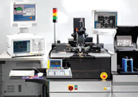
Fig. 1 The automated multiport wafer level measurement system consisting of the probe system, a multiport VNA, calibration substrates, wafer probes, a control PC with software and interfaces between the PC, probe system and VNA.
The calibration software puts all of these components together and the System Settings Wizard simplifies this complex procedure. It automatically runs when the program is activated for the first time and configures the probe system, the VNA and the interfaces.
The physical interface between the control PC, the probe system and VNA can be GPIB, LAN, USB or RS-232. Based on the Virtual Instrument Software Architecture (VISA), the software interface drivers allow the user to freely choose the interface type as well as the model (for example, National Instruments, Agilent, etc.). In addition, a direct link to the company’s probe system and ProberBench™ software over the SUSS Control Interface (SCI) is supported.
Substrate Wizard
A calibration procedure requires well known reference elements to be measured, namely calibration standards. These are fabricated on a wafer — the calibration substrate — which is typically a piece of ceramic having a set of standard groups (open, short, load and line) that are required for different calibration types. The type of calibration substrate, the location of the standards and the position of the substrate on the chuck have to be defined to enable the user to choose the desired standards for system calibration. This is done by the Substrate Wizard.
The specifications of the calibration substrate, standards and matching wafer probes are located in a substrate definition file — the csd-file. This is a source for the Substrate Definition Tree, which is a hierarchical view of the substrate properties and is pictured in Figure 2. There are three branches of the tree: type of standards, definition of the standards and specifications of the standards.
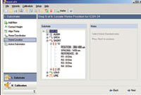
Fig. 2 The Substrate Definition Tree is a hierarchical view of the substrate properties.
Csd-files for all SUSS calibration substrate families are provided with the SussCal“ 6 package. If customized calibration substrates are used or the calibration standards are embedded on the test wafer, the required csd-file can easily be created with a text editor.
The new version 6 of the calibration software can handle an unlimited number of calibration substrates, automatically compensating for their alignment differences from the DUT. Moreover, standards can be picked up from different substrates and used in one calibration project. This allows engineers to define one, two and multiport and/or differential standards within the same calibration project. This is important for measuring components with single-ended or differential inputs or outputs. Also, partially damaged substrates can now be saved for reuse.
To define the substrate required for the calibration, the corresponding csd-file has to be added in the first step of the Substrate Wizard, while the next steps concern the alignment procedure. Alignment defines the physical position of the added substrate on the probe system chuck and saves the substrate contact height (chuck Z-position and the separation value), the rotation angle (the chuck theta) and the X-Y coordinates of the substrate home position. These steps can be repeated if a new substrate has to be added to the list of the active substrates.
Alignment data for each substrate from the active substrates list can be recalled at any time by simply pressing one button. This feature allows fast navigation between different calibration substrates, simple verification of the alignment settings and quick access to the desired calibration standard. As soon as the Substrate Wizard has finished, the user is guided to the final step — the Calibration Project Wizard (CPW).
Calibration Project Wizard
A top-down approach is used in the CPW for defining calibration parameters. The user is guided from the very general level of settings, such as the number of VNA ports, the layout of the DUT ports, the definition of wafer probes and port mapping, to very specific settings, such as the calibration method name and the selection of standards to be measured. The calibration software uses an intelligent control algorithm to prevent users from defining wrong or impossible parameters. It automatically limits the number of choices and steps according to the previously defined parameters and supports the operator using clear and straightforward graphical illustrations.
Figure 3, for example, demonstrates the first step of the Calibration Project Wizard, defining the number of calibration ports, their layout and the selection of the matching wafer probes. It also solves the typical problems of multiport wafer level set up, namely the multiple ways to connect wafer probes to the VNA ports. The VNA port mapping step allows the user to assign the relationship between the selected wafer probe and the VNA port. Therefore, the system can be easily reconfigured without frustrating cable reconnections if the DUT is changed. All-important VNA settings (that is, frequency list, power level, averaging factor, etc.) can be defined within the CPW or can be kept without changes.
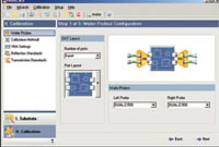
Fig. 3 An example of the first step of the Calibration Project Wizard.
When the desired calibration method is defined, the required calibration standards have to be assigned for the measurements. In contrast to two-port calibration, additional types of calibration standard realization are required. For instance, the four-port SOLT calibration procedure needs six connections of measurement ports (six thru standards). These standards are typically realized in five different types. The user then needs to make sure that the selected thru standard actually connects the correct ports, a very time consuming procedure.
With SussCal“ 6, the standard assignment procedure is visualized by using special graphical components and a drag-and-drop interface. The selected standard is picked up from the substrate definition tree and dropped onto the picture showing the required standards for the defined calibration method (see Figure 4). The standard assignment step of the CPW automatically verifies the selected standard type and the ports connected. In doing so, it prevents the user from selecting a wrong element or connecting the wrong ports.
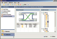
Fig. 4 The selected standard is dropped onto the picture and the available standards for the defined calibration method are shown.
The standard assignment is the last step of the Calibration Project Wizard. Once defined, the calibration data can be saved into a project file, after which the user is guided to the Calibration Control Center.
Calibration Control Center
The Calibration Control Center is designed to make calibration progress control as simple as the operation of an MP3-player, with the operator choosing to start, stop, pause and resume. Also, the sequence for the automated standard measurement can be easily modified, much like a play list. It is possible to run the calibration in manual mode, measuring and re-measuring standards in any desired sequence. Another feature is access-level control whereby engineers can set and lock the test parameters, which then prevent technicians from changing the set up.
Tools
Many tools are available such as the substrate verification tool, which monitors the alignment of the selected substrate from the list of active substrates and helps the user to verify the standard’s quality. As plug-ins, new tools can be simply added to the already installed application at any time.
Conclusion
With SussCal“ 6, the once complex and tedious task of setting up a fully automated calibration process is quick and simple. It easily handles automated testing, and the plug-in architecture ensures maximum compatibility and a stable system with minimum downtime. Running on a standard Windows-PC, the calibration is configured through a logically ordered top-down process. This reduces the time and effort needed for defining the calibration, and significantly increases the accuracy and repeatability of multiport calibration and measurement. Therefore, engineers can be sure that the right parameters will be extracted for device modeling and monitoring production testing will be more efficient.
SUSS MicroTec Test Systems,
Dresden, Germany,
+49 (0) 35240 73-0,
prober@suss.de,
www.suss.com.