
In recent years, wireless communications have progressed very rapidly. Broadband antenna design has become very important for wireless applications. UWB is a high data-rate and short-range wireless technology, utilizing the unlicensed radio spectrum from 3.1 to 10.6 GHz. The UWB antenna is one of the major components of UWB communication systems. Some coplanar waveguide (CPW) antennas have been proposed for wideband application.1–10
The UWB-based systems may be embedded into a variety of portable devices. One of the critical issues in UWB system design is the size of the antenna for portable devices because the size greatly affects the bandwidth and gain. Therefore, the miniaturization of antennas capable of providing a broad impedance matching bandwidth and offering an acceptable gain is a challenging task.2
The UWB antenna plays a unique role because it behaves as a bandpass filter and should be designed to avoid undesired distortions. Some of the critical requirements of a UWB antenna design include: ultra-wide bandwidth, omni-directional radiation patterns, constant gain and group delay over the entire band, high radiation efficiency and low profile. The broadband property and excellent impedance matching of the proposed design lead to desirable performance, such as good antenna gain and radiation patterns. (A planar elliptical monopole antenna for UWB applications was proposed earlier.3)
In this article, a small-size antenna with a CPW feed line for UWB systems is presented. Compared to the planar elliptical monopole antenna, this antenna can produce satisfactory results, such as better gain and good radiation. In this study, a small-size and a good impedance matching of the antenna are obtained and the good radiation characteristics of the constructed prototype are also shown. It is designed to cover the 3.1 to 10.6 GHz UWB band.

The planar rectangle-semicircle-rectangle antenna is etched onto an FR-4 substrate. It is expected that a simple feed and a wide impedance bandwidth are good for practical applications. The simulations and measurement results show that the impedance characteristics of this antenna reduced the ground-plane effect on the performance of a small printed UWB antenna. The performance of the antennas was tested in the frequency domain.
Antenna Design and Experimental Results
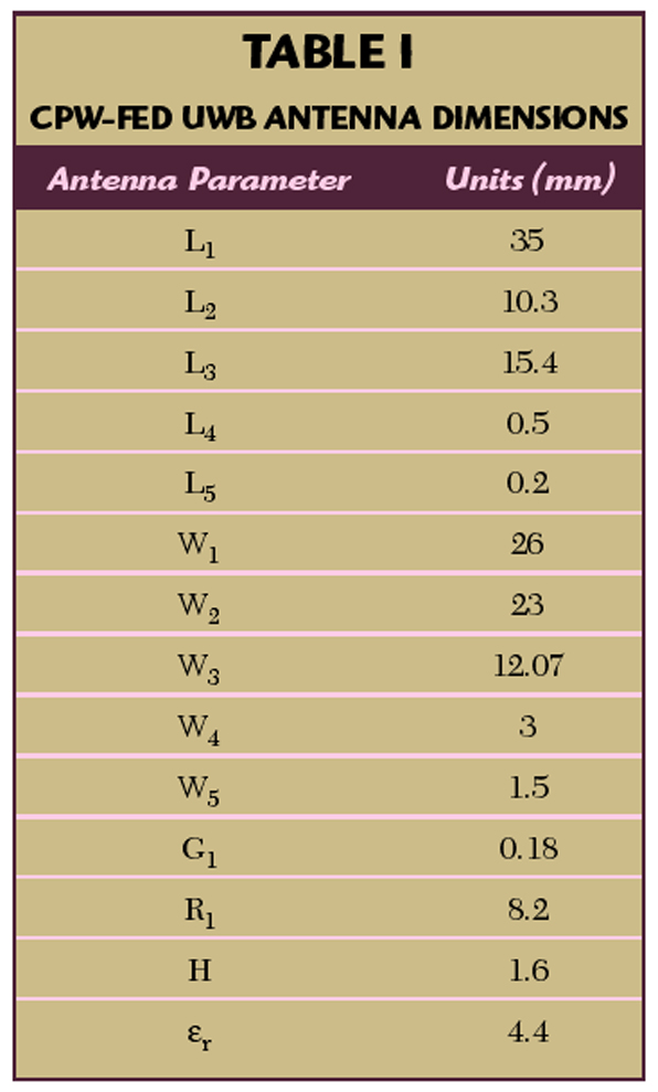
Figure 1 shows the geometry of the proposed UWB antenna and Table 1 lists the antenna dimensions.

The rectangle-semicircle-rectangle shape shown is the radiator of the proposed design. The rectangle of dimension W2 x L2 is located on top of the radiator; the small rectangle of dimension W4 x L4 is located at the bottom of the radiator. A semicircle of radius R1 is inserted between the rectangles to form the radiator.
Two small rectangle metal patches (W3 x L3) on the sides of the antenna serve as capacitive loads. Capacitive loading reduces the input impedance variation with frequency of the antenna. The capacitance can be adjusted by varying the distance between the rectangle patches and the main part of the antenna. The radiator and ground plane were etched on the FR-4 substrate (εr = 4.4 and 1.6 mm thick).
The overall size of the antenna and ground plane is 26 x 35 mm (W1 x L1) and 12.07 x 15.4 mm (W3 x L3). The antenna is excited by a 50 Ω CPW feed line. The width of the center strip (W5) and gap (G1) of the CPW line are 1.5 and 0.18 mm, respectively, to achieve a 50 Ω characteristic impedance.
The spacing between the bottom edge of the tuning stub and the ground plane (L5) is 0.2 mm, which critically controls the impedance matching and the power coupling from the feed line to the tuning stub.
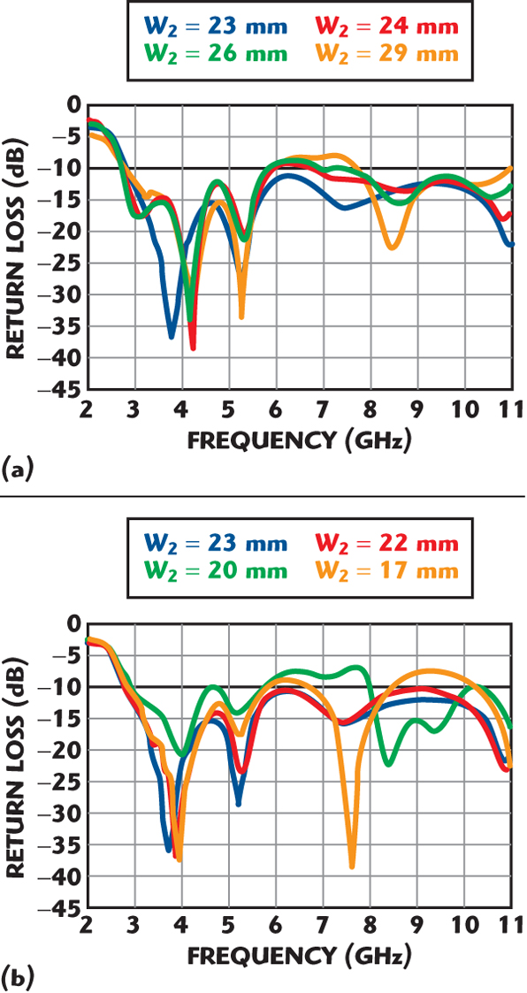
To verify its performance, the proposed UWB antenna was fabricated and measured. Figure 2 shows the measured and simulated return losses. The antenna achieved a –10 dB bandwidth from 3.1 to 11 GHz and covers the band assigned for the UWB applications.1 The return loss of the proposed antenna was measured with an HP-8720ES network analyzer. The excitation source, with a 50 Ω internal resistance, was directly connected between the center strip end and ground planes of the CPW line through an SMA connector and an RF cable to the vector network analyzer.
Usually, the RF cable significantly affects the performance of an antenna under test. It is found, however, that the RF cable hardly affects the lower edge frequency at 3.1 GHz. Figure 3 illustrates the return loss characteristics for different rectangle lengths (W2); all other dimensions remain the same. It is observed that the length of W2 determines the impedance matching in the 6 to 8 GHz band.
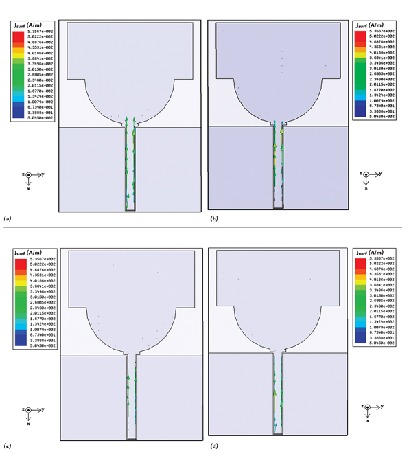
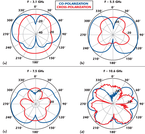
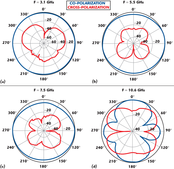
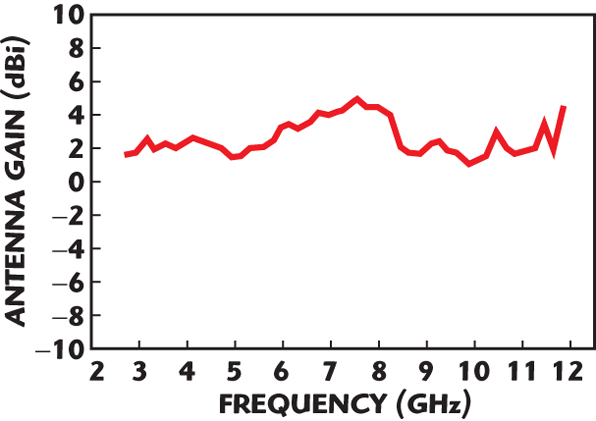
Figure 4 shows the normalized current distributions at four different frequencies. The current density in the center strip of the CPW line and lower edge of the semicircle structure is higher at the lower frequencies. Therefore, the effect from the ground planes on the antenna is small. The radiation patterns were measured at 3.1, 5.5, 7.5 and 10.6 GHz in the x-z plane and y-z plane, and are shown in Figures 5 and 6. The UWB antenna gain is shown in Figure 7.
The maximum gain is most important to evaluate the communication possibility. However, the average gain (2.768 dBi) in the y-z plane should be considered only. This is because the average gain is meaningless in the x-z plane, which has a null point. This plane is similar to the E-plane radiation from a dipole. Therefore, the average gain was calculated only for the y-z plane, with approximately an omni-directional radiation.
In addition, it is expected that, in general, the smaller CPW structure can affect the radiation patterns of the UWB antenna less than the other existing approaches. The measurements show that the antenna has dipole-like radiation characteristics, and the variation in the radiation patterns is slight across the frequency range of interest. This feature provides another important parameter that can be used to change the performance of the antenna. The antenna was designed to have an impedance bandwidth from 3.1 to 11 GHz.
Conclusion
A compact and low-profile planar rectangle-semicircle-rectangle antenna is presented and investigated. It is a good candidate for UWB applications and can be integrated within transceivers. Parametric studies have been done for further investigations of the rectangle-semicircle-rectangle pattern. As a result, the average gain of the antenna has been increased and the ground-plane effect on the impedance response has been reduced.
The performance of the antenna has been evaluated in the frequency domain. The proposed antenna can easily be excited by a 50 Ω microstrip line printed on the FR-4 dielectric substrate and can achieve good impedance matching over the operating frequencies. The proposed antenna design, with good gain, is suitable for UWB applications.
References
1. H. Schantz, “A Brief History of UWB Antennas,” IEEE Transactions on Aerospace and Electronic Systems, Vol. 19, No. 4, April 2004, pp. 22–26.
2. S.W. Su, K.L. Wong and C.L. Tang, “Ultra-wideband Square Planar Monopole Antenna for IEEE 802.16a Operation in the 2 to 11 GHz Band,” Microwave and Optical Technology Letters, Vol. 42, No. 6, September 2004, pp. 463–466.
3. K.C.L. Chan, Y. Huang and X. Zhu, “A Planar Elliptical Monopole Antenna for UWB Applications,” IEEE Conference on Wireless Communications and Applied Computational Electromagnetics Digest, April 2005, pp. 182–185.
4. T.G. Ma and S.K. Jeng, “Planar Miniature Tapered-slot-fed Annular Slot Antennas for Ultra-wideband Radios,” IEEE Transactions on Antennas and Propagation, Vol. 53, No. 3, March 2005, pp. 1194–1202.
5. Z.N. Chen, X.H. Wu, H.F. Li, N. Yang and M.Y.W. Chia, “Considerations for Source Pulses and Antennas in UWB Radio Systems,” IEEE Transactions on Antennas and Propagation, Vol. 52, No. 7, July 2004, pp. 1739–1748.
6. H.G. Schantz, “Introduction to Ultra-wideband Antennas,” IEEE Conference on Ultra-wideband Systems and Technologies Digest, Vol. 16-19, November 2003, pp. 1–9.
7. P.V. Anob, K.P. Ray and G. Kumar, “Wideband Orthogonal Square Monopole Antennas with Semi-circular Base,” IEEE Antennas and Propagation Society International Symposium Digest, Vol. 3, No. 4, July 2001, pp. 294–297.
8. P. Li, J. Liang and X. Chen, “Study of Printed Elliptical/Circular Slot Antennas for Ultra-wideband Applications,” IEEE Antennas and Propagation Society International Symposium Digest, Vol. 54, No. 6, June 2006, pp. 1670–1675.
9. X. Qiu and A.S. Mohan, “The Performance of a CPW-fed Printed UWB Antenna for Wireless Body-worn Applications,” IEEE Antennas and Propagation Society International Symposium, July 2006, pp. 2109–2112.
10. C.Y. Huang and W.C. Hsia, “Planar Elliptical Antenna for Ultra-wideband Communications,” IEEE Transactions on Antennas and Propagation, Vol. 41, No. 6, March 2005, pp. 296–297.
Wen-Shan Chen received his BSc degree in electronic engineering technology from the National Taiwan Institute of Technology (now known as the National Taiwan University of Technology) and his PhD degree from National Sun Yat-Sen University, Kaohsiung, Taiwan, ROC, in 2001. From 2001 to 2002, he was an assistant professor at the Chien-Kuo Institute of Technology, Changhua, Taiwan, ROC. He is currently an assistant professor in the department of electronic engineering at Southern Taiwan University, Tainan, Taiwan, ROC. His research interests include antenna design, RF and microwave circuits.
Kai-Cheng Yang received his MSc degree from the Southern Taiwan University of Technology, Taiwan, ROC, in 2005. He is currently a PhD student in the department of electronic engineering at Southern Taiwan University, Tainan, Taiwan. From 2003 to present, he was engaged in the development of ultra-wideband antennas and ultra-wideband systems. He has conducted research on ultra-wideband antenna characteristics in the frequency and time domains. His current research interests include ultra-wideband antenna design, mobile small antennas and ultra-wideband systems.