
Some methods of antenna modeling and measurement lead directly to radiation patterns and total radiated power without the intermediate, and often tedious or impractical, step of calculating self and mutual impedances.1 Still, it is often desirable and necessary to know the input impedance for each element in the array. This article describes novel formulas for determining the input conductance or resistance without knowing a priori any self and mutual impedances. By determining the conductance, the susceptance is also determined because they are Hilbert transform pairs. Similarly, resistance and reactance are also Hilbert transform pairs.
Formula for Single Antenna

To begin with the simplest case, a single antenna as shown in Figure 1, for which the input voltage V and the total radiated power P is considered.
The radiated power and input voltage are related by the input conductance G, according to the formula

The voltage, in general, is a complex quantity with nonzero amplitude and phase

Using Equation 2, Equation 1 becomes

The first derivative of P is

The second derivative is

Solving Equation 5 for the input conductance yields

Next, Equation 6 is generalized for an antenna array with any number of elements.
Formula for antenna array

Figure 2 shows an antenna array with N elements. The total radiated power P and the input voltages Vn are related to the input conductances Gn according to the formula

The voltages are complex, with nonzero amplitude and phase

Using Equation 8, Equation 7 becomes

According to Equation 9, the first derivative of P with respect to the voltage amplitude at the input of the mth element is

On the right side of Equation 10, the first term is simply the mutual conductance between the mth and nth elements

The voltage amplitudes are determined independently by the sources, so that

Using Equations 11 and 12, Equation 10 becomes

Using Equation 13, the second derivative of P with respect to Am is

The mutual conductance Gnm depends only on the geometry of the array and the wavelength. It is independent of voltage, that is

Using Equations 12 and 15, Equation 14 simplifies to

Solving Equation 16 for the input conductance of the mth antenna element yields

Equation 17 is not only rigorous, it is also intuitively appealing. It proposes that if the amplitude Am of the mth voltage source is perturbed, then the more the total radiated power P is affected, the greater the input conductance Gm must be.
In numerical modeling or experimental work, the second derivative on the right side of Equation 17 may be approximated by finite differences so that

On the right side of Equation 18, P0, P1 and P2 are distinct and separate total radiated powers corresponding to different values of Am. With a little algebra, Equation 18 simplifies to

Formula for Antenna Array with Current Sources
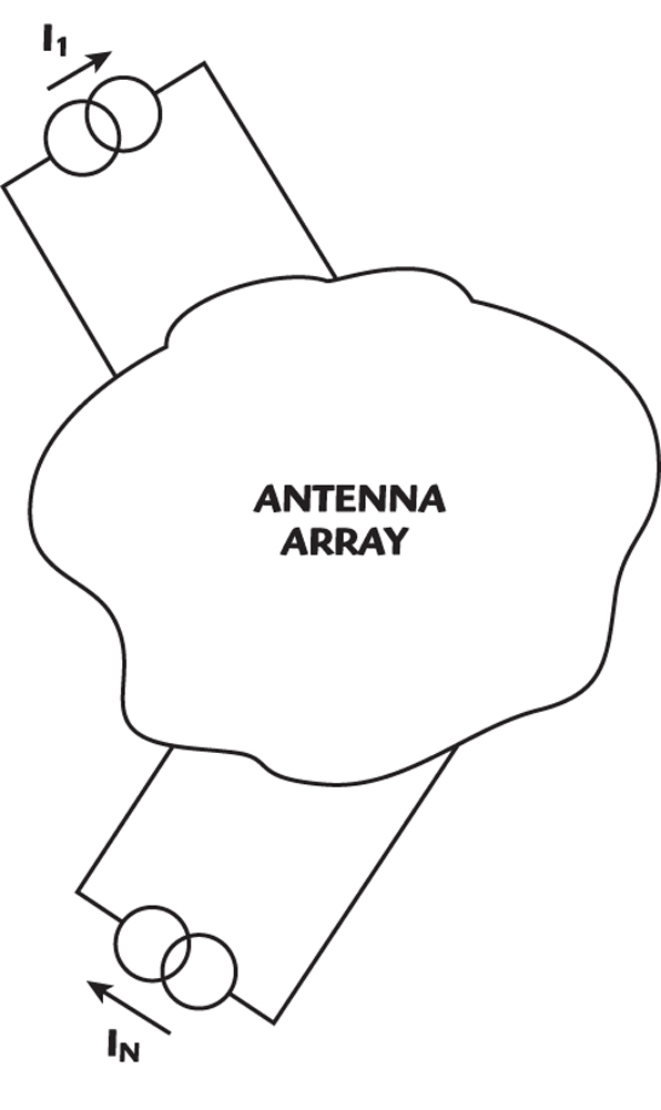
Similar formulas for the input resistance may be derived if the excitations are current sources instead of voltage sources, as shown in Figure 3.
The total radiated power P is related to the current sources In by the input resistance Rn

The currents are complex, with nonzero amplitude and phase

Following steps analogous to those in the previous section, the input resistance to the mth antenna in the array is

Equation 22 is intuitively appealing in the same way as Equation 17. It tells us that if we perturb the amplitude Bm of the mth current source, then the more the total radiated power P is affected, the greater is the input resistance Rm.
Antenna Susceptance and Reactance
So far, the formulas have explicitly described only the real part of antenna input impedance or admittance, that is, the resistance or conductance. Rigorously, however, the imaginary parts have also been determined. This is because the real and imaginary parts of impedance, admittance and of all realizable physical phenomena are not independent. One uniquely determines the other.2 For example, susceptance and conductance determine each other, according to the formulas

Equations 23 and 24 are called Hilbert transform pairs. To make practical use of those equations, B or G must be known over a wide spectrum of frequency

Reactance and resistance are similarly related by Hilbert transforms

In principle, Equations 17 and 23 could be used to determine the antenna input susceptance B. Similarly, Equations 22 and 26 could be used to determine the antenna input reactance X. As a practical matter, however, this mathematical formality is usually not necessary. Antennas can often be regarded as lengths of waveguide or transmission line, and this point of view provides a good approximation to the input susceptance or reactance. It’s the radiation conductance and radiation resistance that are the real (pun intended) challenge.
Conclusion
This article has derived general and powerful new formulas for determining the input conductance (or resistance) for both single antennas and elements in an arbitrarily large antenna array. The formulas avoid the intermediate, and often tedious or impractical, steps of determining self and mutual admittances or impedances. It is necessary only to know the total radiated power and the voltage sources (or current sources).
When the conductance is determined, the susceptance is also determined. Similarly, when resistance is determined, reactance is also determined. This is because they are not independent quantities. They are Hilbert transforms of each other, as are the real and imaginary parts of all physical phenomena. As a practical matter, however, it is usually not necessary to use the formality of the Hilbert transform. For purposes of finding susceptance or reactance, antennas may often be regarded as lengths of transmission line or waveguide.
References
1. J.K. Raines, Folded Unipole Antennas, McGraw-Hill, New York, NY, 2007, Section 2.9 and Chapter 9.
2. S.J. Mason and H.J. Zimmerman, Electronic Circuits, Signals and Systems, Wiley, New York, NY, 1960, p. 351.
Jeremy Keith Raines received his BS degree in electrical science and engineering from MIT, his MS degree in applied physics from Harvard University and his PhD degree in electromagnetics from MIT. He is a registered Professional Engineer in the State of Maryland. Since 1972, he has been a consulting engineer in electromagnetics. Antennas designed by him span the spectrum from ELF through SHF, and they may be found on satellites deep in space, on ships, on submarines, on aircraft and at a variety of terrestrial sites. He may be contacted at www.rainesengineering.com.