
The microwave industry is tied to the birth of radar. Figure 1 is a whimsical look at the birth of radar as portrayed in a 1960s ad for Bomac tubes. In reality, radar was developed primarily at the MIT Radiation Laboratory (RadLab) during World War II. Much of the impetus came from the development of the magnetron in the UK, which was the first source of adequate microwave power and which the British provided to RadLab. There was also work going on at Bell Laboratories, Naval Research Labs and Harvard University.
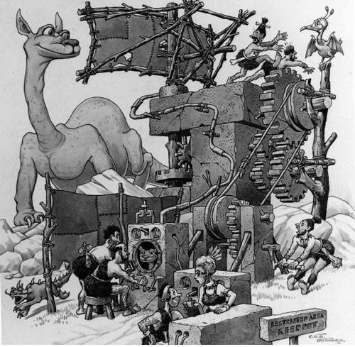
Fig. 1 The birth of radar. (Courtesy of Varian Associates.)
In 1945, at the end of the war and the closing of the RadLab, there were very few active microwave devices. Power sources were limited to triodes, klystrons and magnetrons. The plasma TR tube was the only active switch and the only semiconductors were point contact germanium and silicon diodes. There were no varactors, PINs, bi-polar transistors, FETs, Gunn diodes, IMPATTS or Schottky diodes. Thus, almost all system functions were relegated to passive components. The development of those passive components was the genesis of the microwave industry as we know it today.
The Pioneers
The technical staff at the RadLab was a remarkable collection of highly skilled and motivated physicists and engineers. Much of their work, like that of Julian Schwinger, shown lecturing in Figure 2, endures to this day. Seven of them went on to win Nobel Prizes and five became National Science Advisors. Of more importance to us, many took the entrepreneurial path and started their own companies when the RadLab closed. There were also many large companies that were manufacturing RadLab designed radars. They included RCA, Westinghouse, Raytheon, Sperry Gyroscope and Western Electric, not to mention Bell Laboratories. A number of the engineers in those organizations followed the same path, either joining or starting new companies. Just a few of the notable pioneers and their companies (not in any particular order) include:
Sigurd and Russell Varian – Varian Associates
Henry Riblet – Microwave Development Laboratories (MDL)
Ted Saad – Sage Laboratories
Harold Wheeler – Wheeler Labs (later Hazeltine)
Richard Walker – Microwave Associates
Tore Anderson – Airtron
Art Oliner – PRD
Bruno Weinschel – Weinschel Labs
Marion Hines – Microwave Associates
Joe Saloom – SFD Laboratories
George Southworth – Bell Labs
Bill Mumford – Bell Labs
Seymour Cohn – Stanford Research Institute and Rantec
Leo Young – Stanford Research Institute
George Matthaei – Stanford Research Institute

Fig. 2 Julian Schwinger presents new theory at the RadLab. (Courtesy of MIT Museum.)
Following them was a second wave of younger but still significant contributors too numerous to list.
Transmission Media
The concept of hollow tube waveguides goes back to Lord Rayleigh in 1897; however, the idea was not developed until George Southworth and Wilmer Barrow, after several years of independent research, held separate public demonstrations in 1936. When the rectangular waveguide was employed during WWII, many of the dimensions that became standard waveguide sizes were based on the availability of commercial extruded tubing used for decorative and architectural purposes. While much of the early component development was done in waveguide, its usage today is primarily for high power, millimeter-wave or very low loss applications, since smaller, lower cost techniques have evolved over the years and waveguide has limited bandwidth capability.
Heinrich Hertz demonstrated propagation in coaxial lines several years before Lord Rayleigh proposed hollow waveguides. He also demonstrated the concept of “skin effect,” which showed that high frequency waves only penetrated the conductor to a very limited depth. Coaxial lines had the benefit of complete shielding compared to open wire systems in use at that time. Coaxial lines for short wave radio came into common use in the early 1930s, first as antenna lead-in cables and later as low loss, air dielectric line with bead supports. These air dielectric structures were the basis for the early development of coaxial components. Bandwidth is from DC to some upper frequency where the dimensions permit higher order modes beyond the fundamental TEM mode to propagate.
A variation on coaxial lines is a round or square conductor in between two extended ground planes. This was dubbed ‘Slab-line.’ This configuration allowed access to the center conductor from the side with minimal leakage. Hewlett-Packard produced one of the first coaxial slotted lines using this technique. Slab-line was the basis for many coaxial couplers, hybrids and filters, particularly for test equipment components where high performance was needed. It is still a common media for these components today, although the requirement for precision machining of the parts tends to raise the cost.
The idea of using flat printed circuits at microwave frequencies was first reported by Barrett & Barnes in 1951.1 Bob Barrett was responsible for encouraging research contracts in the field. One of the contractors was Airborne Instruments Laboratory, which developed a printed line on a thin dielectric support suspended between two plates using air as the dielectric. They called it Stripline and registered that name as a trademark. Similar work was also under way at Sanders Associates. They used two boards, one with a pattern and the other as a cover, thus using the boards as the dielectric. They called it Tri-Plate and registered that name as their trademark. They also introduced a product line of circuit modules using the technique, and in 1956 published the Handbook of Tri-Plate Components, which was an invaluable resource for early designers, such as myself. I suspect that they regretted printing it, since there was never a second printing or a second edition. Figure 3 is a photo from the handbook of the products compared to a waveguide assembly.

Fig. 3 A comparison of Tri-Plate Modules to waveguide. (Courtesy of Sanders Associates.)
In 1952, Grieg & Englemann2 of the Federal Communications Research Laboratories published a paper describing a single board with a ground plane on one side and the pattern on the other. They called it Microstrip and also registered the name as a trademark. In due course of time, any printed double ground plane line became described by the generic term “stripline,” the single ground plane became the generic term “microstrip” and the trademarks were ignored.
One of the problems with the new flat transmission lines was the launching connectors. The connectors in use at that time, such as UHF, N, BNC and TNC, were mechanically large and were not constant-impedance designs. The engineers at the Bendix Research Labs developed a small 3 mm connector they called the Bendix Real Miniature (BRM). This was later refined by Omni-Spectra as the Omni-Spectra Miniature (OSM“) and was subsequently produced by many sources as the 3 mm SMA. This development spurred the use of stripline and microstrip at much higher frequencies and spawned the whole new generation of high frequency connectors in common use today.
Passive Components
Hybrids
The workhorse of passive components is the 90° hybrid. It is used in many forms for mixers, switches, diplexing and duplexing, power division, phase shifting and matching reflective circuits. It is a four-port device that provides an even –3 dB split with a 90° phase difference at the output ports with the fourth port isolated. The waveguide sidewall and topwall hybrid was developed in 1950 by Henry Riblet at MDL. Tens of thousands have been sold as investment castings, along with cast bends and other components to be brazed or soldered into waveguide assemblies. Sidewall hybrids have even been fabricated from sheet metal for large waveguides such as the monster WR-2100 hybrid shown in Figure 4. In stripline form, they can be done as direct coupled branch line circuits or as coupled line circuits. The branch arm type has limited bandwidth; however, the coupled line type operates over an octave for a single section. This can be extended by the use of multiple sections and by tandeming sections, thus permitting bandwidths as great as 20:1. Much of this work was done by Joe Mosko at the USN Ordinance Test Station at China Lake, CA. A technique to improve the performance of these multi-section circuits by reducing the discontinuity between sections using non-uniform lines was developed by Carl Tresselt and reported in 1966.3

Fig. 4 A high power duplexer using a sidewall hybrid in WR-2100 waveguide.
While realizing the coupled line hybrid was fairly simple in stripline, it was very difficult in microstrip. This problem was solved in 1969 by Julius Lange at Texas Instruments. He developed an interdigital coupler for microstrip,4 which bears his name and is still used universally.
The companion to the 90° hybrid is the 180° hybrid. It provides an even –3 dB split at 0° phase at the co-linear ports and a similar split with a 180° phase relationship from the difference port. It was invented in its waveguide form in the late 1930s as a bridge by W.L. Barrow, who called it a Magic Tee. It is generally fabricated as a casting, as is the 90° version. In stripline or microstrip, it is usually made as a 1½ ? circumference ring with ports at 0°, 90°, 180° and 270°, and is commonly called a “rat-race” because of its appearance. It is limited in bandwidth like the 90° branch hybrid. A broadband version for stripline was reported by DuHamel and Armstrong in 1965.5 However, to the best of my knowledge, no one has solved the bandwidth problem in microstrip.
Directional Couplers and Power Dividers
Branch arm waveguide directional couplers are frequently used in high power applications, like the ones shown in Figure 5. However, most waveguide couplers are made by utilizing holes or slots in the common wall between two guides. There are a myriad number of these configurations, many of them named after the engineers who first developed them. The Bethe Hole Coupler was reported in the RadLab Series along with many other types. The first multi-hole coupler was described by Bill Mumford in 1944. This was followed by the Schwinger coupler and the Riblet & Saad coupler. Binomial distribution of a large number of holes resulted in very high directivity couplers, which are still used today in most test equipment, where size is not a consideration. TEM Mode couplers in coaxial lines, as well as stripline and microstrip had their start with a single section, quarter-wave coupler, first shown by Harold Wheeler in 1944. This type of coupler has a usable bandwidth of one octave. Many variations were reported through the years. The bandwidth can be extended by using multiple quarter-wave sections, either symmetrically or non-symmetrically. A drawback to multiple sections is decreased directivity due to the discontinuities at the many interfaces. This was improved by the use of non-uniform lines, as previously mentioned and by tapered lines such as the one shown in Figure 6. Unlike stripline, side-coupled lines in microstrip suffered from reduced directivity due to the difference in propagation velocity between the even and odd modes. This problem has been addressed using dielectric overlays and a unique “Wiggly Line” coupler, described by Alan Podell in 1970.6

Fig. 5 High power branch arm couplers in 1?2 height waveguide.

Fig. 6 An asymmetric tapered-line coupler.
Power dividers as we know them today originated in 1960 with the introduction of the Wilkinson divider.7 It was a single section equal N-way divider, matched at all ports with isolation between the output ports. It was limited to one octave bandwidth. In 1965, Parad and Moynihan introduced a similar structure for unequal division.8 Seymour Cohn reported on a multi-section design with multi-octave bandwidth in 1968.9 Figure 7 shows four section dividers built in microstrip.
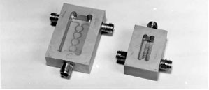
Fig. 7 Four section power dividers.
Filters
More papers and books have been written on the subject of filters than any other passive device. In their review paper on the subject in the centennial issue of MTT-S Transactions, Ralph Levy and Seymour Cohn list 91 references and that was back in 1984.10 However, the “Bible” on the subject was, and still is, Microwave Filters, Impedance-Matching Networks and Coupling Structures by Matthaei, Young and Jones. It was published by McGraw-Hill in 1964. It went out of print briefly but it was rescued and re-printed by Artech House Inc. in 1980. It is still available today and belongs on every engineer’s bookshelf.11
Filters have been made in every conceivable transmission line, from cavities to waveguide and all of the various TEM-mode configurations. Much of the early work was done during WWII at RadLab, Harvard University and Bell Labs, and most modern filter theory is still derived from this early work. There are so many contributors that I cannot distill the work into this short article. I suggest that readers interested in more detail go to the referenced Levy and Cohn paper and start from there.
Ferrites
The first demonstration of a microwave ferrite device occurred in 1949, but practical devices were yet to come. Early devices were based on the principle of Faraday rotation, followed by waveguide isolators of several types. The concept of the three-port circulator was presented by H.J. Carlin in 195412 and was refined for stripline by H. Bosma in 1961.13 In the beginning all these devices were built as single components, mostly because of the large magnetic circuits that were needed to make them work, which made them difficult to integrate. With the increased use of stripline for subassemblies in the ’60s there was a need to be able to integrate ferrites. Melabs (later acquired by Microwave Associates) introduced a line of drop-in circulators with the unofficial name of “Flying Saucers” because of their shape. Figure 8 shows a selection of these circulators. The flying saucer had serious technical problems due in large part to the problem of maintaining ground plane continuity as well as the lack of a magnetic return path, which made them more susceptible to performance variation due to nearby ferrous objects and to temperature changes. In the late ’60s, Ken Carr at Ferrotec (later acquired by Microwave Associates) came up with a technique for direct integration of ferrite circulators in stripline subassemblies. He used a suspended substrate line in a channeled construction. The ferrite disks were mounted in the channels, which were then lapped to provide uniform contact throughout the assembly. By laying out the circuit with alternate directions of rotation, the magnetic path of one circulator was returned through another, thus providing a shielded structure and temperature stability. Figure 9 shows one of these early subassemblies, some of which are still being produced today. However, with the widespread use of microstrip for subassembly work, due to the ease of semiconductor integration, most ferrite components have reverted back to drop-ins, which have been vastly improved over the years.
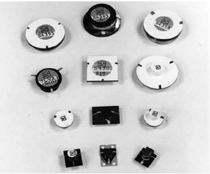
Fig. 8 Early drop-in circulators.

Fig. 9 A Ferrotec stripline assembly with ferrites.
Mixers
Mixers date back to the RadLab. In most cases they were balanced types made by putting diode mounts onto either 90° or 180° hybrids in coaxial lines as well as waveguides. There were some single-ended mixers and at low frequencies some double-balanced mixers were made using transformers. Most of the improvements in mixer technology resulted in the use of new and better diodes to replace the early point contact devices. A major breakthough in microwave mixer design was the multi-octave, doubly balanced mixer introduced by Don Neuf at RHG Laboratories in the early 1960s. He built a 2 to 20 GHz mixer using orthogonal tapered microstrip baluns with a ring of four diodes in the third plane. It was difficult to fabricate, but nothing could touch it for performance. As monolithic ring diode assemblies came along, refinements were made and performance and manufacturability improved. This basic configuration is still the basis for most doubly balanced mixers today, although other configurations such as the star mixer are in use for circuits that require a high IF frequency.
Toroidal Components
Much of the early work on ferrite toroidal transformers was done at Bell Labs for telephone use at low frequencies. Two of the early pioneers in bringing those concepts to the microwave world were Carl Sontheimer and Alan Podell at Anzac and Adams Russell (both companies later merged and were aquired by M/A-COM). Using time domain analysis, Sontheimer made some components with 500:1 bandwidths. Figure 10 shows an early impedance bridge, which worked from 3 to 1500 MHz. As ferrite materials were improved, the upper working frequency for this class of device increased to 6 GHz and higher. However, it was Harvey Kaylie at Mini-Circuits who brought the technology to widespread use through manufacturing techniques and aggressive marketing that resulted in cost reduction and off-the-shelf availability.

Fig. 10 An early transformer bridge.
Conclusion
This brief history is far from complete. I have not addressed rotary joints, electromechanical switches or tubular filters because very little historical material has been published and I do not have any personal experience in those areas. I will be happy to hear from anyone who can enlighten me. What I have done is to try to give a personal view from my areas of experience. For those who would like a more complete and balanced history, there are a number of sources that I have listed below.
Additional Historical Material
- Special centennial issue of IEEE Transactions on Microwave Theory and Techniques, Volume MTT-32, No. 8, September 1984.
- “Five Years at the Radiation Laboratory,” originally presented to members of the RadLab in 1946, reprinted for the 1991 MTT-S International Microwave Symposium, Boston, MA.
- R. Buderi, The Invention That Changed the World, Simon & Schuster, 1996.
- J. Conant, Tuxedo Park, Simon & Schuster, 2002.
- NOVA: Echoes of War, 1990, WGBH, Boston, MA (one hour program, still available on tape).
References
1. R.M. Barrett and M.H. Barnes, “Microwave Printed Circuits,” presented at IRE National Conference on Airborne Electronics, Dayton, OH, 1951.
2. D.D. Grieg and H.F. Englemann, “Microstrip – A New Transmission Technique for the Kilomegacycle L Range,” IRE Proceedings, Vol. 40, 1952, p. 1644.
3. C.P. Tresselt, “The Design and Construction of Broadband High-Directivity 90° Couplers Using Non-Uniform Line Techniques,” IEEE Transactions on Microwave Theory and Techniques, Vol. 14, No. 12, December 1966, pp. 647–656.
4. J. Lange, “Interdigital Stripline Quadrature Coupler,” IEEE Transactions on Microwave Theory and Techniques, Vol. 17, No. 12, December 1966, pp. 1150–1151.
5. R.H. DuHamel and M.E. Armstrong, “A Wideband Monopulse Antenna Utilizing the Tapered-Line Magic Tee,” 15th Annual Symposium, AFAL, Wright-Patterson AFB, 1965.
6. A. Podell, “A High Directivity Microstrip Coupler Technique,” 1970 International Microwave Symposium Digest, G-MTT Symposium, pp. 33–36.
7. E. Wilkinson, “An N-way Hybrid Power Divider,” IEEE Transactions on Microwave Theory and Techniques, Vol. 8, No. 1, January 1960, pp. 116–118.
8. L.I. Parad and R.L. Moynihan, “Split-Tee Power Divider,” IEEE Transactions on Microwave Theory and Techniques, Vol. 13, No. 1, January 1965, pp. 91–95.
9. S.B. Cohn, “A Class of Broadband Three-port TEM-mode Hybrids,” IEEE Transactions on Microwave Theory and Techniques, Vol. 16, No. 2, February 1968, pp. 110–118.
10. R. Levy and S. Cohn, “A History of Microwave Filter Research, Design and Development,” IEEE Transactions on Microwave Theory and Techniques, Vol. 32, No. 9, September 1984, pp. 1055–1067.
11. G. Matthaei, L. Young and E.M.T. Jones, Microwave Filters, Impedance-matching Networks and Coupling Structures, Artech House Inc., Norwood, MA, 1980.
12. H.J. Carlin, “Principles of Gyrator Networks, Proceedings Modern Advances in Microwave Techniques, Polytechnic Institute of Brooklyn, November 1954, p. 175.
13. H. Bosma, “On the Principle of Stripline Circulation,” Proceedings of the IEEE, Vol. 109B, 1961, p. 137.