
The demand for products and systems that can operate at higher frequencies is increasing with the higher frequency bands being utilized for important applications such as vehicle distance radar (77 GHz) and aerospace and defense applications (94 GHz). This creates demand for higher frequency measurement and testing. To address this need Rohde & Schwarz has extended the frequency range of its high-end vector network analyzers to 75 to 110 GHz (W-band), with the introduction of the R&S ZVA-Z110 frequency converter, which is available for the R&S ZVA24, R&S ZVA40 and R&S ZVT20.
A key consideration was to make the frequency converters easy to use and help users save time, which is why it was designed so that no additional hardware is necessary if an adequate four-port vector network analyzer is used to operate a pair of converters. Also significant was the fact that in recent years, multi-port measurements have become more and more important, which is why the R&S ZVA-Z110 is the first to offer full multi-port and balanced measurement in the W-band.
The Converter
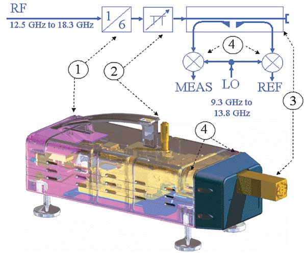
To illustrate how the frequency converter operates, Figure 1 shows a transparent CAD representation of the converter together with its block diagram where: (1) is a source multiplier; (2) is an adjustable waveguide attenuator; and (3) is the directional coupler, which separates the reference and measurement channels. These channels are down-converted using (4) two harmonic mixers. Using the example of a 90 GHz bandpass filter consider the S-parameter measurement of a filter.
Step 1: Configuration and Set Up
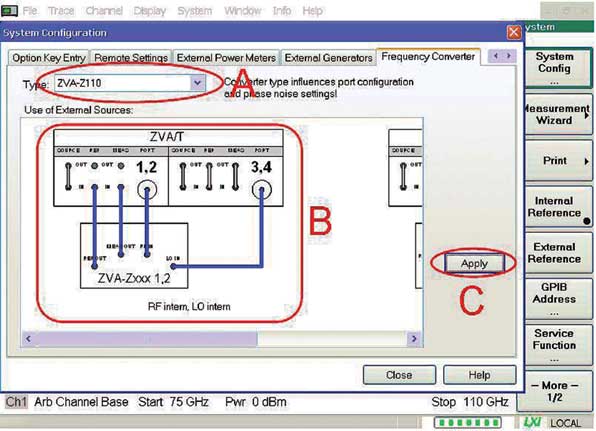
Configuration is as easy as ABC, as Figure 2 illustrates. In this figure A is – select the converter type; B is – choose the cabling scheme; and C is – click, apply and connect the converters to the analyzer (see Figure 3). The frequency axis becomes 75 to 110 GHz (indicated at the bottom of Figure 2). In addition, all measurement parameters for the converters are set automatically (for example, multiplication factors of RF and LO, optimum power levels, redefinition of preset, connector type WR10 and the R&S ZV-WR10 waveguide calibration kit is defined and selected).
Step 2: Calibration
In this example the calibration is performed using the TOSM calibration technique and the R&S ZV-WR10 waveguide calibration kit (shown in the foreground of Figure 3). The kit supports several other calibration techniques such as TRL, UOSM, TOM, TRM and OSM. A sliding match can be included in the kit. The sliding match can be used to raise directivity and load match up to typically 42 and 40 dB. Due to radiation effects that occur at an open end of a waveguide, the open standard, which is known from coaxial calibration kits, has to be replaced by an offset short. The offset short consists of a shim (acts as a λ/4 transformation around the middle of the frequency band) and a short standard.
Step 3: Measurement
Figure 3 shows the complete set up using an R&S ZVA24 vector network analyzer and two R&S ZVA-Z110 converters to measure a 90 GHz bandpass filter. Measurements on high rejection filters require high dynamic range. These frequency converters set a new standard for dynamic range of typically > 110 dB and can easily satisfy the needs for filter measurement. This enables the user to increase the measurement bandwidth to 1 kHz, for example, gaining high sweep velocity.
Besides filter measurements, several other applications can be carried out:

• Tests on low noise amplifiers that can be performed without any problems due to the integrated W-band attenuator, making it possible to provide the low stimulus levels that are essential for this type of measurement.
• The use of the converters in production lines that are dedicated to compact design and fast sweeps. For instance, in particle-sensitive environments, e.g. for a wafer prober, the passive cooling concept without a fan is an additional advantage.
• Multi-port and balanced applications at millimeter-wave frequencies.
Multi-port measurement
Up to now, multi-port and balanced measurements have been restricted to about 50 GHz. Nevertheless, there are a number of applications within the W-band that use balanced circuits or devices featuring multiple ports (for example, the vehicle distance radar and aerospace and defense applications mentioned earlier). The R&S ZVA-Z110 frequency converters and the R&S ZVT20 vector network analyzer have been designed to provide a flexible solution for up to six measurement ports.
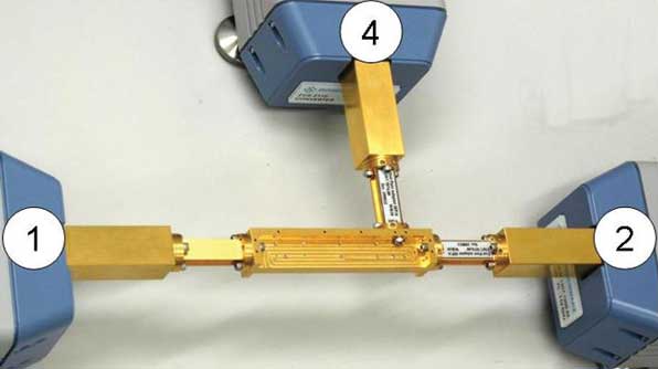
Consider a three-port measurement of a directional coupler. The first question is why use three test ports? The answer is that with three converters and a suitable network analyzer, a three-port coupler can be measured in a single test sequence (see Figure 4). This saves time and allows measurement of all 3 x 3 S-parameters of the coupler, eliminating the need for reconnections and the use of several two-port calibrations. Instead, a full three-port calibration is possible, resulting in more accurate results.
Measurement Set Up
The R&S ZVT20 allows the user to drive up to four frequency converters, without using an external generator. This solution is compact (no additional hardware) and offers fast measurement speed. With this application three converters are sufficient. Test ports 5 and 6 provide the LO signal for the converters. In addition, if needed, external Wilkinson dividers can be used to distribute the LO signal to all converters.
UOSM Calibration
The advantage of the UOSM calibration technique is that it gets along with an unknown through as a calibration standard. This unknown through has to fulfill only one requirement: reciprocity. The unknown through, therefore, does not need to have good matching or low loss. Even low priced waveguide sections, bends and twists with standard flanges meet the reciprocity requirement and can serve as unknown throughs.
Any significant modification to the test port orientation after calibration may cause a (avoidable) loss in accuracy. Therefore, an H-plane bend is used in this example to establish the throughs between waveguide test ports 1 and 4, and test ports 2 and 4. The through between waveguide test ports 1 and 2 is made by direct connection of the two test ports.
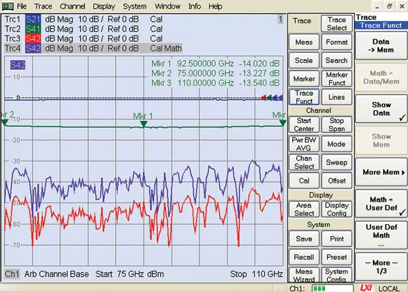
The measurement results for the directional coupler are shown in Figure 5 and are measured using a measurement bandwidth of 1 kHz. Trc1 shows the insertion loss, Trc2 the coupling loss, Trc3 the isolation and Trc4 is the directivity calculated by means of trace mathematics from Trc3 and Trc2.
Configuration Issues
An R&S ZVA or R&S ZVT vector network analyzer with an upper frequency limit of at least 20 GHz can be used to operate the converters, so long as the direct generator/receiver access and converter control software options are adopted. Another configuration issue is whether an external generator is necessary.
In the second example (coupler), a four-port R&S ZVA can be used alternatively if the converters’ LO signal is provided by an R&S SMF100A signal generator and distributed to all converters (for example, by a four-port power splitter). The external generator has to be controlled by the R&S ZVA. This causes a growth in sweep time, which can be minimized by the use of the generator’s listed sweep mode. As a general rule, the number of converters operated by the network analyzer can be increased if the external generator is used to provide the LO signal.
For example, six frequency converters can be operated using an R&S ZVT20, an R&S SMF100A and a suitable LO distribution network. Also, a two-port R&S ZVA24 vector network analyzer, which is normally not sufficient to drive a converter (at least four ports are required), can be complemented by an R&S SMF100A to operate one or two converters. Table 1 shows the key specifications of the R&S ZVA-Z110.
Conclusion
The fact that equipment and systems are being employed at higher frequencies for an increasing number of applications has created a demand for the R&S ZVA-Z110 frequency converter to extend measurement options into the 75 to 110 GHz (W-band) range. As this article has demonstrated its implementation opens up greater possibilities for vector network analyzers.
Europe:
Rohde & Schwarz, Munich, Germany
+49 1805 12 4242
customersupport@rohde-schwarz.com
Americas:
Rohde & Schwarz
+1 888 837 8772
customersupport@rsa.rohde-schwarz.com
Asia:
Rohde & Schwarz
+65 65130 488
customersupport.asia@rohde-shwarz.com
RS No. 300
Further reading
Readers wanting more information can access data sheets and application notes from www.rohde-schwarz.com.
For readers generally interested in the field of vector network analysis the book Fundamentals of Vector Network Analysis is recommended and available via the book shop at www.books.rohde-schwarz.com.