
Microwave laminates, or substrates, have been used in the industry for approximately 50 years. Although they can be thought of as the materials used in microwave printed circuit boards, they do far more than provide mechanical support for components and copper interconnections. In a real sense, these materials form components in their own right, as their characteristics determine the geometry of the circuit, and material selection will substantially affect the circuit performance. Figure 1 shows a broad summary of how these materials have evolved over the past 50 years.
Traditionally, these laminates have been constructed from composites based on a polytetrafluoroethylene (PTFE) resin and some form of reinforcement and/or filler. Ceramic materials such as alumina have been and continue to be used in microwave applications. Continuing pressure to reduce costs in the industry, however, has led to a trend towards traditional PCB processing methods and towards composite laminates, though certainly not in all applications.

PTFE has excellent electrical properties, but is both mechanically and thermally unstable. In the early years, reinforcement was provided by glass, either woven into mats, or in the form of microfibers, which were randomly distributed throughout the PTFE matrix. In the 1970s, laminate manufacturers began to introduce particles of ceramic filler, which could be used to vary relative permittivity, and give the material additional mechanical stability. However, PTFE continued to suffer from electrical properties, which varied over temperature, an issue that was addressed in the 1980s by the addition of new ceramic fillers. PTFE-based materials continue to be used today in a wide variety of applications, but in the 1990s their dominance was challenged by a new generation of hydrocarbon-based materials that offered low loss PTFE-type performance but which could be processed much more like the standard FR4.
Key Material Parameters
Traditionally, the two most important electrical parameters are the dissipation factor (tan δ) and the dielectric constant or relative permittivity (εr). A low tan δ allows for circuits with low insertion loss and high Q factors in resonant circuits. Commonly available materials have values of εr between 2.1 and 10.8, and the choice of higher or lower εr is usually made with a mind towards the circuit dimensions. However, the εr tolerance is of critical importance, with most materials achieving between ±1 to 3 percent.
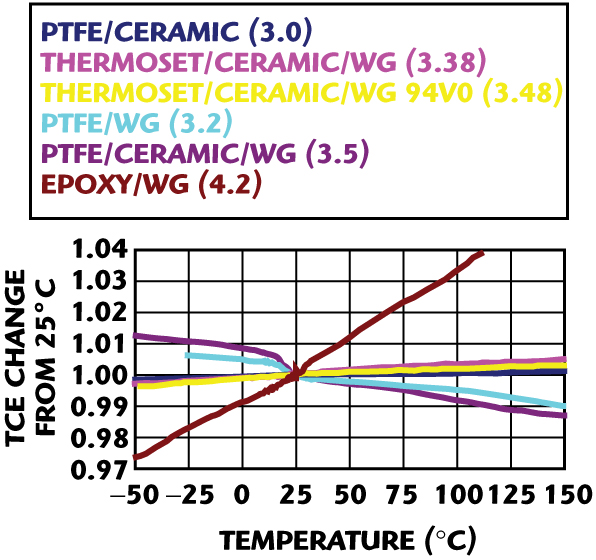
Over the years, other parameters have gained in importance and materials have evolved to meet those needs. Having a low thermal coefficient of dielectric constant (TCE) indicates that the dielectric constant varies little over temperature. Figure 2 illustrates the different TCEs for various materials. Of increasing importance is the material’s thermal coefficient of expansion (CTE). Having X and Y CTEs closely matched to that of copper improves the flatness and dimensional stability of a material, while matching it also in the Z-axis improves the reliability of plated through holes (PTH), as the laminate and the plated copper expand and contract at the same rate through temperature variations. Thermal conductivity remains a key specification in applications where high power is used and thermal management issues provide challenges to the designer.
As the use of microwave technology in commercial and consumer applications has increased, there has been more focus on ease of processing. This has long been an issue with PTFE-based materials, which require special through-hole activation prior to plating and demand more careful handling, resulting in a small group of PCB manufacturers specializing in fabricating PTFE circuits. A range of hydrocarbon materials was launched, in order to facilitate the use of larger, general-purpose PCB substrates in higher volume commercial applications. These are compatible with FR4-type processes and complex multilayer designs. They also allow engineers to mix and match microwave materials and FR4 in the same multilayer, enabling the use of the more expensive laminates for higher frequency circuits and antennas, while using less expensive FR4 for lower frequency signals and power distribution.
Automotive Applications
Microwave technology is being adopted in the automotive industry in a variety of applications and each makes different demands on the materials employed. Examples are electronic toll collection (ETC) and its technological offspring dedicated short-range communication (DSRC) system, long-range radar sensors for adaptive cruise control (ACC), short-range radars for a variety of safety and convenience features, satellite TV and radio, and various other communications technologies, which are being implemented in cars, such as GPS navigation, cellular systems and WiFi.
Electronic Toll Collection

ETC systems are now being applied worldwide for payment collection from vehicles traveling on or through specific roads, bridges and tunnels. The technology has now settled on 5.8 GHz in Europe and Asia and 5.9 GHz in North America, and is actually an adaptation of the military identification friend or foe (IFF). The system is divided into roadside units or readers, which are usually mounted on gantries over the road, and transponders or tags, which are mounted in the area of the car windshield. As the car passes under the gantry, the tag is interrogated and the driver’s bank account is debited by the appropriate amount. The key differences between the tag and reader technologies are driven by volume.
Tags are produced in millions per year, readers in thousands. Consequently, cost pressure is far higher on the tags, and this is reflected in their design. Most are relatively simple double-sided PCBs, containing a backscatter antenna, a diode detector and often some kind of IC. Lower performance requirements and short track lengths lead to most designs using simple FR4 glass/epoxy materials. Occasional versions appear where performance dictates using a material with lower loss. In these cases, PTFE materials may be used, but hydrocarbon-based materials tend to be preferred as they pass easily down the production lines of the kind that high volume PCB manufacturers use to produce these components.
The approach to designing readers is somewhat different. Individual designs may be manufactured in quantities of thousands, and most of a system’s intelligence is therefore built into these roadside units and this obviously has an impact on design goals. The transceivers require a range of RF circuitry, amplifiers, filters, etc., plus a separate antenna, which is usually also designed on a PCB. Both low loss and tight control of dielectric constant are important, and many designs have settled on PTFE-based materials for these reasons.
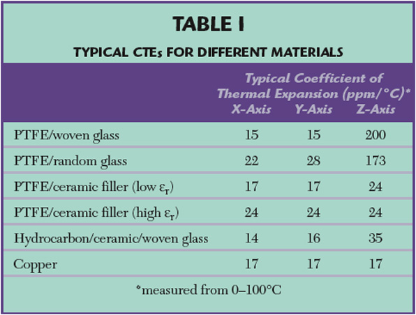
In an effort to save space and reduce assembly costs, many reader designs have integrated all the RF circuitry and antenna functions onto one multilayer board. Figure 3 shows a typical configuration of a four-copper layer reader, where layer 1 is the RF circuitry, layer 4 is the antenna, and layers 2 and 3 would be additional circuits at lower frequencies. Interconnection of the layers would be through plated through holes. Given the probable temperature fluctuations of systems situated outdoors, a key material consideration would be the Z-axis CTE, and the match between the dielectric material and copper (see Table 1). In these designs, the processing issues surrounding PTFE may not be so much of an issue, as volumes are lower, and specialist PTFE processing facilities may be used, as long as PTFE-based laminates with lower CTEs are selected.
Some attention should also be paid to the choice of bondply that is used to bond the two laminates together and sits between layers 2 and 3. If a low loss material is required here, then a bondply system similar to the laminate should be used. However, if the central two layers are predominantly carrying low frequency signals or are ground planes, it may be possible to save money and use a simple FR4 prepreg as a bonding film. In these cases, it may be wiser to consider the more rigid, hydrocarbon-based laminates, due to greater mechanical compatibility with FR4.
Satellite Radio and TV Antennas
While it would be difficult to cover entirely the wide range of antennas now being deployed on cars, two of the applications, which normally require high frequency materials, are those used in satellite radio and TV antennas. While not being fundamentally different in principle to those used outside cars, satellite radio antennas are usually patch antennas designed on thick laminates to achieve the required bandwidth. Typically, an εr between 3 and 6 is used to achieve a balance of low cost (high εr is more expensive) and compact size.
Despite a preference for low loss and tight εr control, cost is a primary driver. Part of the challenge is that bandwidth requirements often demand a laminate thickness of between 3 and 6 mm, and conventional materials are laminated from plies that link cost directly to thickness. Therefore, achieving a design with reduced thickness can be highly desirable. There are no particularly stringent processing issues, so PTFE is frequently used, though rigidity is sometimes an issue, as some car manufacturers have elaborate packages that locate satellite radio, GPS and cellular phone antennas in the same roof mounted casing.
While still in its infancy, satellite TV used in cars is beginning to grow, primarily in the US. While the LNB employed in a car may not be especially different than in a domestic set up, the obvious impracticality of a dish means that electronically steered, roof mounted antennas are essential. Traditional satellite systems operate at around 10 GHz, with newer high definition systems running at over 20 GHz, so using low loss materials with tight εr control is essential. Typically, PTFE laminates are used to achieve the lowest loss, though hydrocarbon-based laminates may also be acceptable.
Initial systems focus on a multilayer design carrying the antenna elements on top and a feed network on the bottom. Few if any plated through holes are employed. Because of low volumes today, maximum focus is on achieving performance goals. However, these antennas contain few components and processing is relatively straightforward; therefore, the total cost of an antenna/feed combination is heavily dominated by laminate cost. The next generation will be geared to achieving cost targets, which will, by necessity, mean that lower cost materials must be used, if car satellite TV is to become affordable.
Radar Sensors
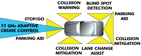
One of the most interesting growth areas for microwave technology in cars today is radar sensors. For several years now, many of the more exclusive cars have been available with adaptive cruise control, in which the car maintains a constant distance from the vehicle in front, instead of a constant speed, as is the case with conventional cruise control. This is achieved using a narrow band 77 GHz long-range radar system to track the position and speed of the car ahead. More recently, short-range radars operating at 24 GHz have been introduced, which can be used for a variety of functions such as parking assist, braking assist, stop-go systems for use in traffic jams, collision mitigation in which safety systems such as air bags and seat belts are pre-activated an instant before a collision, and various other functions (see Figure 4).
There remains some discussion about which frequency bands will remain available in different parts of the world and there is a possibility that, in some areas, these short-range sensors may have to move to 79 GHz, but for the next few years, 24 GHz will dominate. This has a significant impact on the choice of technologies employed in the sensors, particularly the semiconductors, which are mostly GaAs but likely to move to SiGe for new designs. It also has a strong impact on material choice for the PCBs. Reducing cost is key if these sensors are to move beyond the realm of luxury cars and into the mass market.
In the past, there has been no real use of the 24 GHz technology for consumer products, though the latest generation of satellite television LNBs operates at similar frequencies in the US. Radar sensors at 24 GHz generally include an MMIC or two, associated RF circuitry, an antenna and digital signal processing. The trend is strongly towards additional integration for reasons of size reduction and lower cost manufacturing. Current designs follow an approach of having a four-layer multilayer board, not unlike those in auto-tolling roadside units. However, the electrical parameters involved are more critical at 24 GHz.
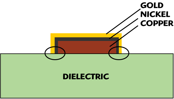
The dielectric constant needs to be tightly controlled, as filter tolerances are more critical. The dielectric losses are higher at higher frequencies and copper losses are also more important. At 24 GHz, the skin effect is greater, leading to more current being carried at the base of the copper tracks, so having copper with a smoother surface is advantageous. The effect of copper surface treatment on the performance of a circuit is often overlooked. This is because at higher frequencies, much of the current flows not only along the bottom surface of the conductor, but a higher proportion of it also flows along the edges. Thus, the current can flow predominantly through the metal, which is plated on top of the copper tracks.

Figure 5 illustrates a cross-section of a typical copper track plated with nickel and gold, showing the main area of current flow. Thus, the conductivity of the surface finish can have a significant effect on insertion loss. Figure 6 shows the insertion loss of a 50 Ω line on a 0.020" RO4003 laminate clad with standard foil, using different surface finishes by comparing electroless-nickel-immersion gold, hot-air-solder-leveling, silver and bare copper. It can be seen that the commonly used nickel-gold process, despite its other benefits, has a negative effect on insertion loss at the frequencies used by automotive radar sensors.
In principle, applications can be found for short-range radars that would allow for between 2 to 10 sensors per car to be fitted, which translates to a potential for many tens of millions of sensors per year. In such volumes, material cost is critical, as is the cost of manufacturing. High frequency performance may demand high frequency materials, but cost pressures demand that they be used in conjunction with conventional FR4 whenever possible, usually in multilayer boards that employ both materials. Thus, the selection of a microwave laminate will include consideration of its mechanical properties such as CTE and dimensional stability, with a view to matching them as closely as possible to FR4. Furthermore, the potentially high volume of these products means that microwave laminates should be compatible with standard FR4 processing, enabling the use of high volume PCB fabricators, qualified by the automotive industry for all its other rigid board manufacturing. This has resulted in a trend towards the hydrocarbon-based laminates and away from PTFE with its specialist processing requirements.
The same cannot be said of PTFE when considering materials for long-range radar sensors operating at 77 GHz. At such high frequencies, losses on hydrocarbon-based materials are often considered too high to be acceptable, and most designs are either on PTFE-based laminates, ceramics, or occasionally on the new generation of liquid crystalline polymer (LCP) materials. Materials with a dielectric constant of 3 or less are chosen because they permit track widths that can be processed reliably and because they have the lowest dissipation factor.
Consideration is also given to the type of reinforcement used in PTFE laminates. The very small wavelengths involved raise the importance of material isotropy, because circuit designs can be sensitive to small local variations in dielectric constant that can be found in woven glass reinforced products. Thus, the trend is towards materials with smaller glass or ceramic fillers that are randomly distributed inside the PTFE matrix. The total absence of any filler or reinforcement is one of the attractions of the LCP product. The previously mentioned issue of copper conductivity becomes more complicated at 77 GHz, where smoothness is commonly regarded as even more critical, but is not necessarily so.
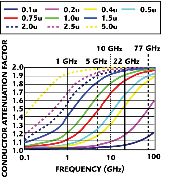
Figure 7 shows the theoretical effect of copper roughness on conductor attenuation over a wide frequency range. Most commercially available coppers used on PCB materials vary in RMS roughness from approximately 0.4 μm, for treated rolled copper and reverse-treated electrodeposited copper (ED), to 5 μm for the roughest ED coppers. The shiny side of ED or rolled copper can be as smooth as 0.1 μm RMS. As can be seen from the graph, at 77 GHz almost all copper should behave as though it is essentially rough, due to resistivity saturation effects. However, very recent studies have cast some doubt on this and the best current advice would be to use copper that is as smooth as possible, though the benefit may not be as pronounced as it is at 10 to 20 GHz, for example.
Conclusion
In some respects, it would be easy to view current trends in the automotive industry as little more than the adoption of technology that has been used for some years. It is true that applications have existed at K-band and W-band for many years. However, it is clearly the case that automotive applications at 5.8, 24 and 77 GHz, for example, will drive developments in low cost, high volume technology in ways that cellular radio previously did below 2 GHz and satellite TV LNBs did at 10 GHz. This poses challenges for designers seeking to implement previously exotic technology for everyday use, but also for materials companies seeking to develop products that facilitate the commercialization of such designs. Today, some new cars possess technology that until recently was only dreamt of in fighter aircraft. It is reasonable to believe that in 10 years time, this will be true of the majority of cars in production.

John Hendricks received his BSc degree in physics from Manchester University, England, UK, in 1984. He then joined Marconi Defense Systems where he worked as a microwave engineer, before moving to the Test and Measurement Division at Rohde & Schwarz. In 1990, he joined Rogers Corp., where he currently works as the market development manager in the Advanced Circuit Materials Division.