
Bandstop filters (BSF) play an important role in rejecting higher harmonics and spurious responses for microwave and millimeter-wave applications. The conventional method to implement bandstop filters involves the use of shunt stubs or stepped-impedance microstrip lines with large circuit size.1 To reduce the filter area, certain slow-wave structures, such as open-loop resonators, are widely adopted.2
Recently, some periodic structures such as electromagnetic bandgap (EBG),3 defected ground structure (DGS)4 and left-hand material5 exhibit good bandstop characteristics and are popularly applied to the design of bandstop filters. Their stopband bandwidth and sharp cut-off frequency response are enhanced by using four or more cells; however, this leads to a larger size and more transmission loss in the stopband. Moreover, EBG and DGS require an etching process on the backside ground plane and additional position calibration, which increases time-consumption and adds difficulties in machining.
A spurline is a simple defected structure, which is realized by etching an L-shaped slot in the microstrip line. It provides excellent bandgap characteristics and can be applied to antenna and filter designs.6,7 However, very limited research on its equivalent circuit has been reported. In this article, an equivalent circuit model of a spurline in a microstrip structure will be derived, based on circuit analysis theory and verified by electromagnetic (EM) simulations. Two compact microstrip BSFs using spurline and cross-junction open stubs will then be designed, fabricated and measured. The measurements verify the validity of this methodology. Finally, conclusions are given.
Circuit Modeling of a Spurline
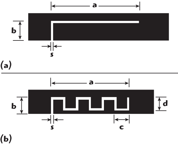
Based on previous work,8 a schematic view of spurlines is shown in Figure 1. The configuration of the proposed spurline is described by the slot width s, the slot length a and the slot height b. The meander line has two adjustable parameters, c and d. In general, the slot gap provides a capacitive effect while the narrow line exhibits an inductive effect. A meander line provides a slower-wave effect than the straight slot.
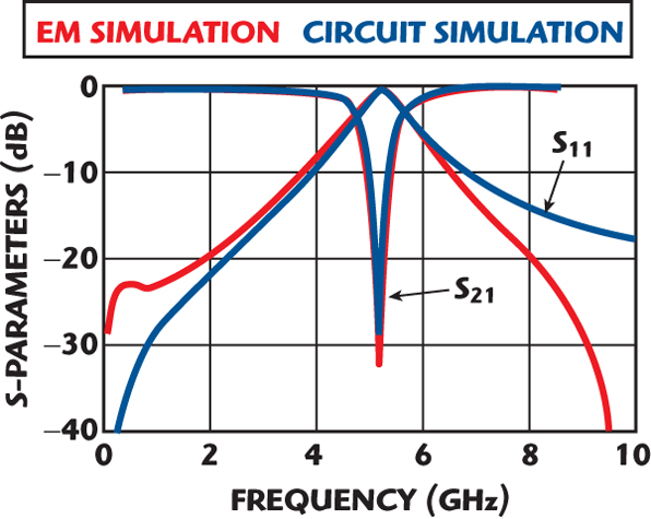
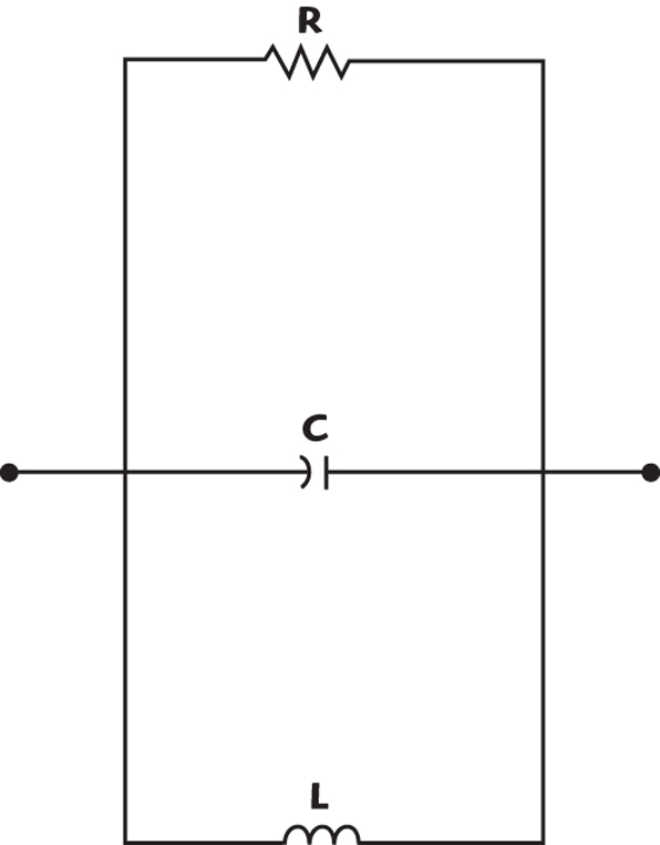
To study the spurline’s transmission characteristics, it was simulated with Ansoft Ensemble 8.0. The dimensions of the spurline structure are s = 0.1 mm, a = 9 mm and b = 0.4 mm. A Rogers TMM10 substrate, with a relative dielectric constant of 3.38 and a thickness of 0.508 mm, is used in the simulations and measurements. The spurline is etched on a 50 Ω microstrip line with a width of 1.17 mm and its frequency characteristics are shown in Figure 2. There is an obvious bandgap at the resonant frequency of 5.17 GHz. A simple circuit model with one LCR-network resonator for a spurline is proposed in Figure 3. The resonant characteristics are modeled by one LC-resonator and the radiation effect and loss are considered by including a resistor, R. Based on transmission line theory and the spectral domain approach, the circuit parameters can be extracted using the following equations.
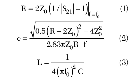
where

Z0 = characteristic impedance of the transmission line (50 Ω)
f0 = resonant frequency
S21 = insertion loss
Δf = –3 dB bandwidth of S21
Based on the simulated results, the extracted circuit parameters are L = 0.5626 nH, C = 1.6818 pF and R = 3.9032 kΩ. The circuit simulation, using Agilent ADS, has been compared previously to the EM simulation. From 0.1 to 10 GHz, a good agreement between the EM and circuit simulations can be observed.
Bandstop Filter and Results
Two new BSFs were designed by employing one spurline structure on a 50 Ω microstrip line with a pair of cross-junction open stubs. The design flow of this filter proceeded as follows.
First, the start point is to design the spurline resonator at f0. This resonator can be modeled by the LC model. f0 is controlled by the slot width s, the slot length a and the slot height b. Then, constructing the open stub, which works as a capacitor, follows. The length of the open stub is chosen to improve the stopband’s bandwidth and is adjusted using ADS.
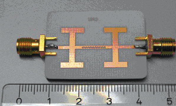
The open stub geometry is determined by l1 and l2, while the distance between the two open stubs is l3. Fourteen is the distance between the left open stub and the spurline. The 50 Ω microstrip line has a width of w. The structure of the cross-junction open stubs is optimized using ADS. The physical parameters l1, l2, l3, l4 and w of this BSP are chosen to be 10, 2, 12.1, 1.2 and 1.17 mm, respectively, as shown in Figure 4. The physical parameters l1, l2, l3, l4, l5 and w, of the second BSP, with a meandered spurline, are chosen to be 7, 8, 2, 2.4, 13 and 1.17 mm, respectively, with the dimensions of the meander spurline being s = 0.2 mm, a = 7.9 mm, b = 0.8 mm, c = 0.7 mm and d = 0.6 mm. Its photograph is shown in Figure 5.

The filters characteristics were simulated and compared with measurements. In Figure 6, the measured results show that the filter with a straight spurline has a stopband from 2.84 to 6.02 GHz with S21 less than –20 dB. Furthermore, it is found that two transmission poles are located at 4.7 GHz with S21 = –66 dB and at 5.3 GHz with S21 = –71 dB.
The deep bandstop characteristics are excellent for practical engineering applications. In addition, the total length of this BPF is 17 mm, which is approximately λg/6 (λg is the guided wavelength at the –3 dB cut-off frequency). Without any periodic structures, the circuit size is reduced dramatically. Good agreement between EM simulations, circuit simulations and measurements validate the proposed design methodology of the microstrip BSF with a spurline structure.
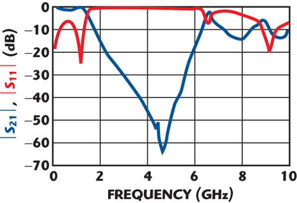
In Figure 7, the measured results, for the BSF with a meandered spurline, show that the filter has a stopband from 2.3 to 5.6 GHz with S21 less than –20 dB. The maximum insertion loss within the passband is 1.0 dB. Furthermore, there are two transmission zeros on the stopband. They are –54 and –63 dB at the frequencies of 4.3 and 4.6 GHz, respectively. The measurements were performed with a vector network analyzer (HP8722D) over the frequency range 0.1 to 40 GHz.
Conclusion
This article describes simple and compact BSFs that were implemented and measured. The filters consist of one spurline and a pair of cross-junction open stubs. The bandstop characteristics of this spurline at its resonant frequency is characterized with one LCR-resonator and good agreement between EM and circuit simulations, based on the extracted parameters, was demonstrated.
The proposed BSFs were measured and show that excellent bandstop characteristics are obtained. The proposed circuit model of a spurline will help in developing microwave circuits by computer-aided design (CAD) techniques and the new BSF can be widely used for harmonics suppression in microstrip circuit applications.
Acknowledgment
This work is supported by State 973 Program (No.: 2006CB302900), China.
References
1. J.S. Hong and M.J. Lancaster, Microstrip Filters for RF/Microwave Applications, John Wiley and Sons Inc., New York, NY, 2001.
2. J. Shi, J.X. Chen and Q. Xue, “Compact Microstrip Low Pass Filter with Wide Stopband Integrating a Bandstop Structure in an Open-loop Resonator,” Microwave and Optical Technology Letters, Vol. 47, 2005, pp. 582–584.
3. S.Y. Huang and Y.H. Lee, “A Tapered Small-size EBG Microstrip Bandstop Filter Design with Triple EBG Structures,” Microwave and Optical Technology Letters, Vol. 46, 2005, pp. 154–158.
4. J.S. Lim, Y.T. Lee, C.S. Kim, D. Ahn and S. Nam, “A Vertically Periodic Defected Ground Structure and its Application in Reducing the Size of Microwave Circuits,” IEEE Microwave and Wireless Components Letters, Vol. 12, No. 12, December 2002, pp. 479–481.
5. F. Martin, F. Falcone, J. Bonache, R. Marques and M. Sorolla, “Miniaturized Coplanar Waveguide Stopband Filters Based on Multiple Tuned Split Ring Resonators,” IEEE Microwave and Wireless Components Letters, Vol. 13, No. 12, December 2003, pp. 511–513.
6. C. Nguyen and K. Chang, “On the Analysis and Design of Spurline Bandstop Filters,” IEEE Transactions on Microwave Theory and Techniques, Vol. 33, No. 12, December 1985, pp. 1416–1421.
7. S. Hong and K. Chang, “Single-feed Triple-frequency Rectangular Microstrip Patch Antenna with Pairs of Spurlines,” Electronics Letters, Vol. 42, 2006, pp. 673–674.
8. H.W. Liu, Z.Q. Cheng and L.L. Sun, “Dual-mode Triangular-patch Bandpass Filter Using Spurlines,” Electronics Letters, Vol. 42, 2006, pp. 762–763.

Hai-wen Liu received his BS degree in electronic systems and his MS degree in radio and remote-sensing science from Wuhan University, Wuhan, China, in 1997 and 2000, respectively, and his PhD degree from Shanghai Jiao Tong University, China, in 2004. From 2004 to 2006, he was a research assistant professor at Waseda University, Japan. From 2006 to 2007, he was with Technische Universitat Hamburg-Harburg and Kiel University, Germany, as a Humboldt research fellow. He is currently a professor at the Institute of Optics and Electronics, Chinese Academy of Sciences, Chengdu, China.

Zhiguo Shi received his BS and PhD degrees from the department of information and electronic engineering, Zhejiang University, China, in 2001 and 2006, respectively. He is currently a post-doctor at the same university.

Reinhard H. Knoechel received his Dipl.-Ing degree in electrical engineering and his Dr.-Ing degree from Technische Universitat Braunschweig, Braunschweig, Germany, in 1975 and 1980, respectively. He has held the chair in microwave engineering at Technische Fakultat, Christian-Albrechts University of Kiel, Kiel, Germany, since 1993. His research interests include active and passive microwave components, microwave measurement techniques, industrial microwave sensors and radar.

Klaus F. Schuenemann received his Dipl.-Ing degree in electrical engineering and his Dr.-Ing degree from Technische Universitat Braunschweig, Braunschweig, Germany, in 1965 and 1970, respectively. He has been a full professor of electrical engineering and the director of Arbeitsbereich Hochfrequenztechnik, Technische Universitat Hamburg-Harburg, Germany, since 1983. His interests include nonlinear microwave circuits, semiconductor device modeling, solid-state oscillators, digital communication systems and integrated-circuit technologies.