
Recently, there has been much research on broadband and multi-band antennas for various wireless communication systems. The ultra-wideband (UWB) regulation released by the Federal Communications Commission (FCC) in 2002, “UWB Technology,” holds great promise for a vast array of new applications that have the potential to provide significant benefits for public safety, businesses and consumers in a variety of applications, such as radar imaging of objects buried under the ground or behind walls and short-range, high speed data transmissions.
The UWB systems have been allocated the frequency band from 3.1 to 10.6 GHz.1,2 However, within the UWB frequency band, there is a wireless local area network (WLAN), which operates from 5.15 to 5.825 GHz and may cause interference with the UWB operations. A band-reject filter is therefore necessary in the RF circuit, although this will introduce complications for UWB systems.
A shielded stripline-fed UWB antenna was proposed,3 without a band-reject function, while its overall dimensions were 35.5 x 20 mm. A planar elliptical ring antenna, operating from 4.6 to 10.3 GHz, was also described,4 with dimensions of 29 x 26 x 2.36 mm. A planar triangular monopole antenna was reported,5 with an impedance bandwidth covering from 3.25 to 7.55 GHz and dimensions of 25 x 28.5 x 1.27 mm. A triangular monopole antenna with an impedance bandwidth from 4 to 10 GHz was described in the literature.5

A UWB antenna, with a band notch characteristic,7 used a slot-type split ring resonator to reject the existing WLAN frequencies but caused the antenna gain to be less than 4 dBi. The dimensions of the CPW-fed printed antenna described by Xiaoning and Mohan8 are 63.5 x 30 x 1.524 mm with a dielectric constant of 3.38. It has only half radiation patterns. As a result, these antennas with large size, insufficient bandwidth and/or with directional radiation patterns are not suitable for mobile applications of UWB systems.
The CPW-fed antenna has the advantage of ease of fabrication, small size and wider bandwidth. It has been popular for various applications due to its low radiation losses, lightweight and compatibility with integrated circuits. In this design, to achieve the required bandwidth for UWB applications, a pair of the symmetrical notches is placed at the two corners of the ground plane. Furthermore, by inserting a straight slit at a proper location on the ground plane, the band-reject function can be obtained to suppress the 5.10 to 5.81 GHz band.
In this article, a novel rhombic CPW-fed antenna is presented, with a small size of 28.5 x 17 x 0.8 mm, for use in UWB applications with band-reject function. The proposed antenna has the advantage of low cost, small size, omni-directional radiation patterns and ease of fabrication. These features and the small size make it attractive for mobile phone, laptop, receivers and UWB applications. Details of the antenna design and experimental results are presented and discussed.
Antenna Design
The proposed antenna configuration is shown in Figure 1. Its dimension are Wsub = 28.5 mm, Lsub = 17 mm and H = 0.8 mm. The coplanar waveguide-fed antenna is printed on an FR4 substrate with a relative dielectric constant εr = 4.4. The CPW-fed line is connected to a 50 Ω standard miniature adapter (SMA). The antenna structure is selected to be a rhombic patch with dimensions of P1 = 12.02 mm, P2 = 9.62 mm and the flare angle of the antenna is α = 90°.

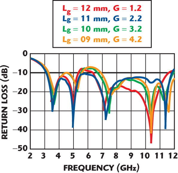
The feed gap distance G is the distance between the radiation patch and the top edge of the ground plane. It determines the impedance matching, as shown in Figure 2. The width Wg and length Lg of the symmetrical ground plane on the proposed antenna are 6.5 and 11 mm, respectively. By cutting the symmetrical two notches of proper dimension W1 x L1 at the upper corner of the ground plane, it is found that a broader bandwidth can be achieved for the proposed antenna.
This phenomenon occurs because the two notches affect the electromagnetic coupling between the radiation patch and the ground plane, which enhance the impedance matching bandwidth. In addition, the use of a straight slit, inserted into one of the ground planes, yields the band-reject characteristic. The length L2 = 8 mm was chosen to reject the limited band of 5.1 to 5.81 GHz, that is approximately λg/4 at the center frequency of the rejected bandwidth (λg = λ/ εeff). The rejected frequency bandwidth is determined by the width of the slit W2, which is 0.5 mm. This antenna was constructed and experimentally studied and the measured results are given in the following section.

Experimental Results and Discussion
CPW-fed monopole antennas with various parameters (W1, Lsub and L2) were constructed and studied to demonstrate the proposed bandwidth enhancement technique and band-reject function. The simulated results are obtained with Ansoft High Frequency Simulation Software (HFSS). Figure 3 shows the measured return loss for different width W1, the other dimensions being Wsub = 17 mm, Lsub = 28.5 mm, H = 0.8 mm, G = 2.2 mm, Lg = 11.mm, Wg = 6.5 mm and L1 = 5 mm. With the symmetrical notches width chosen as 1 mm, the –10 dB impedance bandwidth for the optimal proposed antenna is from 3.1 to 11.9 GHz.
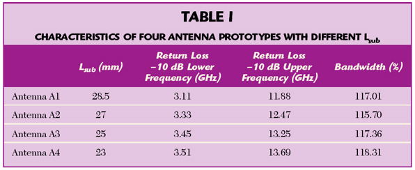
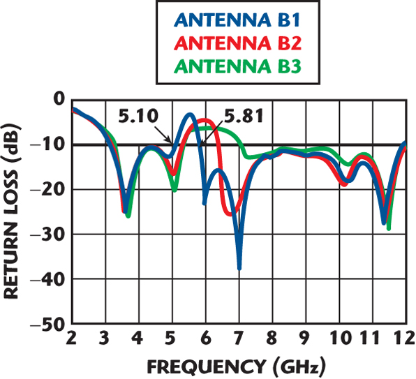
From the experimental results shown in Figure 4 and Table 1, as the length of Lsub increases, the lower frequency is slightly higher and the upper frequency markedly increases. In this case, the other dimensions were: Wsub = 17 mm, H = 0.8 mm, G = 2.2 mm, Lg = 11 mm, Wg = 6.5 mm, L1 = 5 mm and W1 = 1 mm. The length of the substrate determines the lower frequency (fs) and is equal to λg/2. Figure 5 shows the measured return loss for various length of L2. The other antenna dimensions are: Wsub = 17 mm, Lsub = 28.5 mm, H = 0.8 mm, G = 2.2 mm, Lg = 11 mm, Wg = 6.5 mm, L1 = 5 mm, W1 = 1 mm and W2 = 0.5 mm.
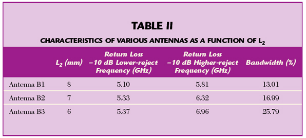
By embedding a straight slit in one of the ground plane, a 5.10 to 5.81 GHz rejection band was created. The related results are also listed in Table 2. The measured and simulated return losses for the proposed antenna designs A1 and B1, with optimal dimensions, are shown in Figure 6. The slight differences between the measured and simulated results are caused by fabrication variations.
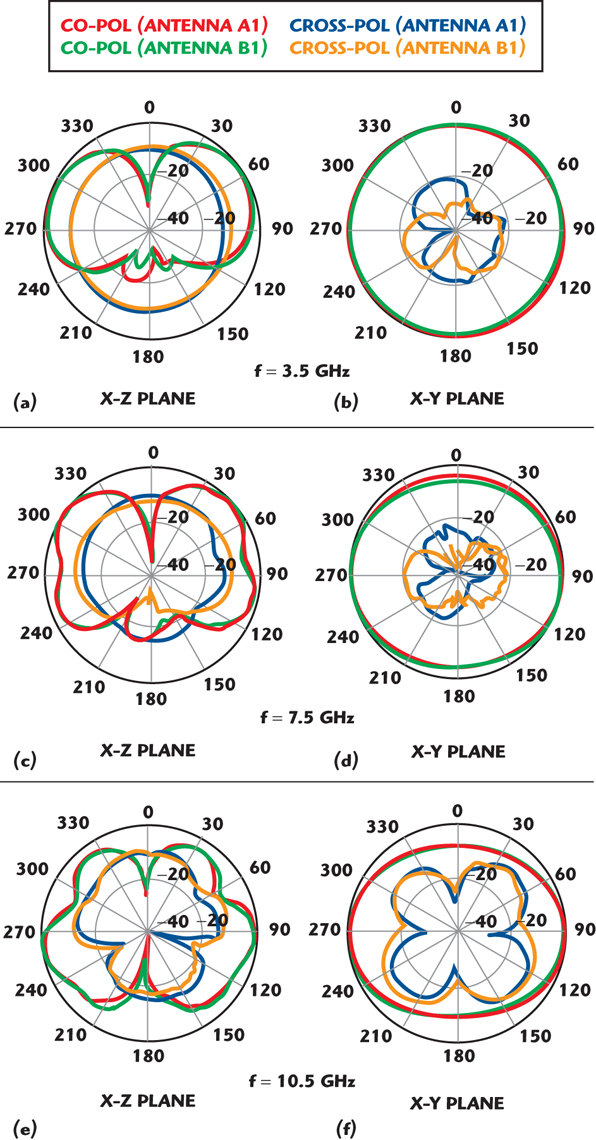
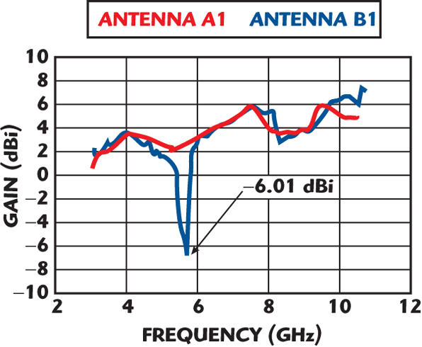
The far-field radiation patterns were measured and calibrated in an anechoic chamber. Figure 7 shows the measured radiation patterns with and without the slit at 3.5, 7.5 and 10.5 GHz in both the X-Z and X-Y planes. Since the CPW-feed line is located parallel to the Z-axis, the X-Z plane radiation pattern of the proposed antennas has nulls in the Z-direction. In the X-Y plane the antennas are nearly omni-directional even at the higher frequencies. Figure 8 shows the measured antenna gains versus frequency. The measured peak antenna gain for the antenna with slit (B1) is 7.54 dBi at 10.6 GHz.
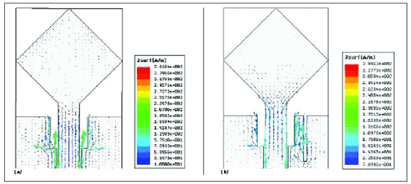
Figure 9 shows the simulated surface current distribution at 5.45 GHz for the proposed antennas with and without a slit. These currents are concentrated near the notches in the UWB structure. Furthermore, in the UWB structure with a slit, the surface currents are partly concentrated on the ground plane, causing the band-reject characteristic. As shown, the proposed antenna has good radiation characteristics.
Conclusion
The proposed antenna A1 exhibits a broad bandwidth of approximately 118 percent (3.1 to 11.9 GHz) for a –10 dB return loss and a good radiation performance, while retaining a small volume (28.5 x 17 x 0.8 mm). It uses a rhombic shape radiating patch and notches on the ground pads to achieve a broadband impedance match.

The proposed antenna B1, with a straight slit embedded at the upper edge of one of the ground planes, shows a rejected 5.125 to 5.825 GHz band. The CPW-fed monopole antenna has a simple structure with low profile and small size. Both the proposed antennas (A1 and B1) maintain nearly omni-directional radiation characteristics over the operating frequency. They will be attractive candidates for UWB applications.
References
1. B. Piernas, K. Nishikawa, T. Nakagawa and K. Araki, “Improved Three-dimensional GaAs Inductors,” 2001 IEEE MTT-S International Microwave Symposium Digest, Vol. I, pp. 189–192.
1. UWB R&O News release v3, (2002).
2. P. Li, J. Liang and X. Chen, “Study of Printed Elliptical/Circular Slot Antennas for Ultra-wideband Applications,” IEEE Transactions on Antennas and Propagation, Vol. 54, 2006, pp. 1670–1675.
3. B. Sanz-Izquierdo, P.R. Young, Q. Bai and J.C. Batchelor, “Compact UWB Monopole for Multilayer Applications,” Electronics Letters, Vol. 42, 2006, pp. 5–7.
4. Y.J. Ren and K. Chang, “Ultra-wideband Planar Elliptical Ring Antenna,” Electronics Letters, Vol. 42, 2006, pp. 447–449.
5. J.R. Verbiest and G.A.E. Vandenbosch, “Small-size Planar Triangular Monopole Antenna for UWB WBAN Applications,” Electronics Letters, Vol. 42, 2006, pp. 566–567.
6. C.C. Lin, Y.C. Kan, L.C. Kuo and H.R. Chuang, “A Planar Triangular Monopole Antenna for UWB Communication,” IEEE Microwave and Wireless Components Letters, Vol. 15, 2005, pp. 624–626.
7. J. Kim, C.S. Cho and J.W. Lee, “5.2 GHz Notched Ultra-wideband Antenna Using Slot-type SRR,” Electronics Letters, Vol. 42, 2006, pp. 315–316.
8. Q. Xiaoning and A.S. Mohan, “The Performance of a CPW-fed Printed UWB Antenna for Wireless Body-worn Applications,” 2006 IEEE Antennas and Propagation Society International Symposium Digest, pp. 2109–2112.
Wen-Shan Chen received his BS degree in electronic engineering technology from the National Taiwan Institute of Technology (now National Taiwan University of Technology) and his PhD degree from National Sun Yat-Sen University, Kaohsiung, Taiwan, ROC, in 2001. From 2001 to 2002, he was an assistant professor at the Chien-Kuo Institute of Technology, Changhua, Taiwan, ROC. He is currently an assistant professor in the department of electronic engineering at Southern Taiwan University (previously Southern Taiwan University of Technology), Tainan, Taiwan, ROC. His research interests include antenna design, RF and microwave circuits.
Yen-Hao Yu received his BS degree from Chung Hua University, Taiwan, ROC, in 2006. He is currently a graduate student in the department of electronic engineering at Southern Taiwan University. His main research interests include printed antennas for wireless communications, especially printed antennas for UWB and WiMAX applications.