
A variety of commercial, governmental and military applications utilize the 4.40 to 4.99 GHz band. In the US and NATO countries, the 4.4 to 4.5 GHz band is designated for military fixed and mobile communications such as point-to-point microwave links and telemetry applications such as unmanned aerial vehicles (UAV), commonly known to the general public as drones. In the 4.635 to 4.685 GHz band the United States Navy operates the Cooperative Engagement Capability (CEC) network, which is a radar information distribution network. There is also a radio astronomy service (RAS) globally allocated on a secondary basis in the 4.80 to 4.94 GHz band. More recently, the FCC allocated 50 MHz in the 4.940 to 4.990 GHz band for public safety applications.
Any state or local government agency including municipal utilities can utilize this “new” band on a shared basis. Communication networks deployed in the 4.940 to 4.990 GHz band must be related to the protection of life, health or property and cannot provide services that are otherwise commercially available to the public. These communication networks specifically serve state and local governmental organizations such as police, fire, and search and rescue. Figure 1 is a diagram showing these frequency allocations.
Driven by a growing public awareness for the need to have better emergency communication systems, the 4.9 GHz band is experiencing a rapid increase in available radio products that can be deployed. Thus far, most of the deployments in the 4.9 GHz band have been utilizing the 4.940 to 4.990 GHz spectrum for microwave backhaul link activity with less activity occurring on the access side. These links serve several communication networks including building-to-building, linking temporary stations to a base station and linking remote devices such as video surveillance cameras or SWAT vans to a headquarters. These networks can also be utilized for temporary monitoring of large events, homeland security and for border control activities. Municipal utilities can utilize these networks for remote monitoring and communications. A diagram showing some of these applications can be seen in Figure 2.
Meanwhile, this new 4.9 GHz band is very attractive to public safety communications users for numerous reasons. As a licensed band, one of the greatest advantages to the 4.9 GHz allocation is the minimal interference for public safety users relative to the level occurring in the unlicensed bands such as 5 GHz. Additionally, these networks are easy and fast to deploy with a wide selection of equipment already available. This new FCC allocation of 4.940 to 4.990 GHz permits public safety agencies to implement on-scene wireless networks for video, Internet and database access, transfer of data and files such as maps, building layouts, medical files, police records and missing person images. This allocation also allows public safety agencies to establish temporary (up to one year) fixed microwave links to support surveillance operations and emergency communications.

The FCC licensing rules grants a public safety agency authorization to use the total 50 MHz of spectrum within its jurisdiction. Fixed point-to-point operation requires an individual license for each station, allowing for temporary operations (up to one year) on a primary basis, or for permanent operations on a secondary basis. The FCC has concluded that Part 90 (FCC specifications governing private land mobile radio services) will guide this allocation and declined to adopt any standard for broadband technology.
Antenna Impact on Network Performance
From an equipment perspective, the technical specifications are favorable to the development of networks based largely on the existing inventory of commercially available radio equipment. While there are a number of good radios available from companies for the 4.940 to 4.990 GHz public safety band, antenna selection is by far the most critical decision relative to network performance. Because the antenna cost is a fraction of the radio cost, the antenna system offers perhaps the best return on investment (ROI) of any network component. Selecting and deploying the optimum antenna is critical to ensuring maximized network performance. In fact, choosing the right mix of antennas can lead to significant cost savings in a network. Designers can maximize the coverage for each antenna and minimize interference, thus minimizing the number of radio points required. For point-to-point links the focus will be on microwave parabolic dishes and for point-to-multipoint networks the focus will be on sector antennas. Figure 3 is a diagram showing the two applications.
For the public safety band, a sliding scale power limit depending on signal bandwidth is specified. The antenna gain limit is specified at 9 dBi. However, high power devices used for point-to-point or point-to-multipoint (both fixed or temporary) may use transmit antennas with directional gain up to 26 dBi at maximum transmitter output power. Directional gain may exceed 26 dBi if both power transmitted and spectral density are reduced by the amount that the directional antenna gain exceeds 26 dBi.

Antenna Considerations
There are four basic styles or types of antennas utilized for the 4.9 GHz band. These four can be seen in Figure 4. The sector (hub) antenna is designed to provide segmented coverage over a selected area. They typically provide a wider beamwidth than parabolic antennas and are commonly manufactured in beamwidths of 40°, 60°, 90° and 120°. The flat panel antenna is ideal when aesthetics are critical. They are light in weight and visually appealing, allowing for easy concealment. They are generally available in several sizes and for all broadband wireless bands. Network developers should be aware that parabolic antennas will have more gain for the same size flat panel. This is due to the inherent higher efficiency of the parabolic antenna design.
The standard in microwave antennas is the parabolic or “dish” antenna. The parabolic antenna consists of a parabolic shaped reflector, which focuses energy at the feed point of the antenna. They have a very narrow beamwidth that focuses energy at a specific point, making them ideal for point-to-point communications. Due to the narrow beam, they have a relatively high gain compared to other types of antennas. There are also high performance versions that utilize a shroud and absorber material to improve sidelobe performance and the front-to-back ratio of the antenna. At lower frequencies, that is, below 5 GHz, the behavior of a parabolic reflector can be simulated using a “grid” of reflective elements. This arrangement reduces wind loading, but does not provide the pattern performance or gain as can be achieved with a solid reflector. Additionally, grid antennas are limited to a single polarization.
Different system applications each require a different antenna type to ensure optimum network performance. A point-to-point application requires an antenna with a narrow beamwidth in both planes and high gain. This capability allows for longer paths, as well as minimization of interference. Thus, a parabolic is the best choice. A high performance (HP) parabolic should be utilized whenever interference may be present and the best possible communications path is called for. Due to the crowded nature of spectrum these days, increasing numbers of network designers must utilize HP dishes on microwave links even in the 4.9 and 5.2 GHz bands. These HP dishes allow more links to co-exist in the same geographic area.
Improving Antenna Performance
A common technique to minimize interference is to simply utilize a larger diameter antenna. The larger the antenna, the lower the back lobe and sidelobes will be relative to the main lobe. Additionally, the larger the antenna the higher the gain provided by the antenna. This will lead to a higher received level for the desired signal and a reduced level for the interfering signals. There have been cases where users have resolved interference problems simply by replacing an existing antenna with a larger diameter antenna at a site. Given the expenses associated with the deployment of a microwave link, utilization of a larger diameter antenna is a relatively low cost method to improve network performance. Network developers will need to consider a number of factors including performance, size, weight and cost in their antenna selection process. Users should also always consider the use of radomes to protect their investment for years to come from the elements.
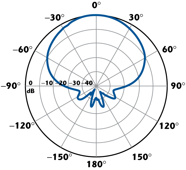
A point-to-multipoint hub (base station) application requires an antenna with a wide horizontal beamwidth and high gain to properly illuminate the coverage area, which is best provided by a sector antenna. A typical sector antenna horizontal pattern can be seen in Figure 5. A point-to-multipoint subscriber application requires a small antenna that can be easily installed and is aesthetically pleasing. This can best be accomplished with a small 1' or 2' parabolic. When selecting the beamwidth for the hub (base) antenna users should consider 90° horizontal beamwidth antennas as the optimum choice with at least 16 dBi of gain or more. Intuitively, it may seem that a network covering 360° would require three 120° antennas. This actually turns out to be inefficient. If a network were to “overlay” three 120° antennas, there would be significant overlap in the three beam patterns. By utilizing three 90° antennas, the area is fully covered, there is less wasted overlap and the higher gain of the 90° antennas helps the system to work over longer distances. Thus, 90 degree sectors are the ideal choice for most hub antenna applications in this frequency range.
Network designers need to be careful if selecting sector antennas that make use of PC board material for the radiating elements or feed system. Typically, low cost antennas have poor or unreliable performance characteristics such as high loss and interference as well as inappropriate beam widths. All too common in low cost PCB antennas is the usage of lower quality board material that has higher losses. As the RF signal travels through the board, more energy is converted to heat and less energy passed through the circuit to eventually be radiated as energy from the antenna system. A higher quality board material will lower the losses and have higher antenna efficiency ultimately providing more energy that is radiated out of the antenna system as true gain.
When selecting antennas, one should also be careful of “paper specs” in a catalog, as there is no agency or industry organization that monitors and qualifies that a manufacturer’s data is correct. It is not uncommon to find antennas that do not meet the gain specified by the manufacturer. It is advisable to visit the manufacturer’s facility and actually witness the antenna gain being measured. Designers should also be careful to check the manufacturer’s warranty. Considering the potentially harsh conditions that the public service band equipment is expected to operate in without failure, equipment quality needs to be adequately addressed. Equipment reliability in the field should be backed by a minimum five-year warranty.
Dual-polarized antennas may be utilized to offer system capacity enhancement with a radio such as Motorola’s Canopy Backhaul PTP400 and PTP600 series or polarization diversity to enhance the link performance. In the case of the radio produced by Exalt Communications, the polarization can actually be switched remotely with a software controlled RF switch. Either of these radios would ideally be matched with an antenna such as the HPD4-5.2, which is a high performance, 4' dual-polarized parabolic dish. By utilizing the combination of one of these radios and a high performance dual-polarized antenna, network performance is thus greatly enhanced and susceptibility to interference greatly reduced.
Conclusion
Radio links in the 4.9 GHz band have many interesting applications in the commercial, government and military sectors. The newly licensed public service band is critical to assisting agencies tasked with dealing with man-made and natural disasters. Antenna selection is often the most cost-effective tool for enhancing system performance. Choosing an antenna that focuses energy to the desired area is key to assuring minimal interference. Higher gain (larger diameter) antennas have narrower beamwidths that help to reduce interference from unwanted sources and maximize desired signal. Choosing an antenna with good efficiency is also critical to assuring optimized performance. As the most significant performance improvements are achieved by optimizing performance of antenna systems, it is imperative that designers consider the choice of antennas carefully. Antenna manufacturers such as Radio Waves are ready to provide an arsenal of antennas to solve complexities facing designers in optimizing their networks at 4.9 GHz and beyond.