
A great deal of attention has recently been paid to ultra-wideband (UWB) technologies for short-range and high data-rate wireless personal area networks (WPAN). By supporting data rates up to several hundred megabits per second (Mbps), these technologies are expected to be used in multimedia consumer electronic products in the near future.
Multi-band orthogonal frequency division multiplexing (OFDM), which is employed for this research, was one of the proposed high rate WPAN standards managed by the IEEE 802.15.3a.1 Direct conversion receivers (DCR) mainly utilize various types of sub-harmonic mixers, such as a resistive mixer,2 a double-balanced active mixer,3 a cascode FET mixer,4 or an anti-parallel diode-pair (APDP) mixer.5
Among these mixers, the APDP sub-harmonic mixer is the most likely to be used for a DCR because it requires no DC power, consists of a simple circuit and shows excellent isolation at the RF, LO and baseband (BB) frequencies. The APDP sub-harmonic mixer can also overcome two serious DCR problems. One is the DC offset created by self-mixing of the LO and RF signals and the other is the even-order distortion created by the second-order intermodulation (IM2).5
This article describes the design and implementation of a new sub-harmonic quadrature mixer for the UWB Mode 1 that operates over the 3 to 5 GHz band. The proposed mixer comprises APDPs, an in-phase power divider, miniaturized bandpass filters (BPF), low pass filters (LPF) and a wideband 45° Wilkinson power divider. The mixer design is presented in detail, along with a discussion of the measured results.
Design
Sub-harmonic Quadrature Mixer
There are two ways of generating in-phase/quadrature-phase (I/Q) signals, that is implementing a quadrature of the phase shift for an either RF or LO port.6 In this article, the quadrature of the LO signal is done at the second sub-harmonic frequency, due to the presence of a non-information signal at a frequency lower than that of the RF signal.
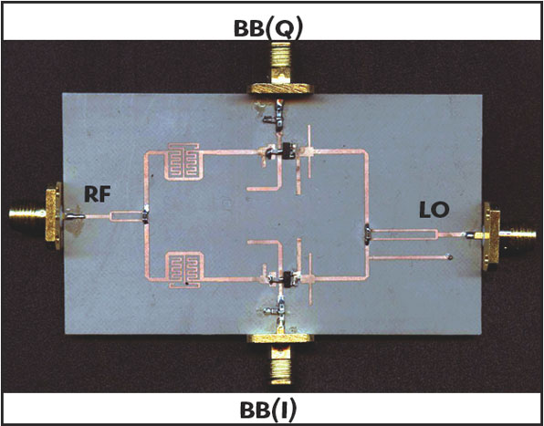
As shown in Figure 1, the proposed hybrid microwave integrated-circuit (HMIC) mixer needs BPFs, LPFs, an in-phase power divider and a 45° power divider. Among these, the BPF and 45° power divider are novel components that greatly contribute to the RF-LO isolation and I/Q mismatch of the circuit; consequently, they are discussed in detail.
In addition, the APDP circuit has impedance matching and isolation blocks for RF and LO, as shown in Figure 2. To isolate the RF port from the LO port, the mixer adopts λRF/4 and λLO/4 open-stubs between the APDP and matching networks. The matching circuits were simply designed with a single-stub matching technique to improve the conversion loss.
The complete mixer circuit is fabricated on a Taconic CER-10 substrate with a dielectric constant of 9.5 and a thickness of 0.635 mm. The high dielectric constant of the substrate affords a compact circuit structure. An Agilent Schottky diode pair (HSMS-2822) is used as the mixing component.
Bandpass Filter
Figure 3 shows a general microwave BPF using transmission-line stubs in a parallel configuration. The BPF was employed to accommodate a high rejection of the LO from 1.55 to 2.4 GHz and a low insertion loss at RF from 3.1 to 4.8 GHz. The design procedure of the BPF follows three steps.
First, a distributed high pass filter comprises a cascade of short-circuited stubs for UWB filters.7,8 The characteristic impedances of each short-circuited line are initially calculated as described by Hong and Lancaster.9 Second, to minimize the parasitic effects of the via holes used as a short circuit, the short-stub is replaced with a double length open-stub. Finally, the shunt open-circuited stubs are meandered to widen the bandwidth of the LO rejection frequency using the coupling between the stub-lines10 and to reduce the filter size to 13 x 7 mm.
Figure 4 shows the simulated and measured results of the new BPF. An insertion loss (S21) of 1 ±0.5 dB and a return loss (S11) of less than –15 dB are obtained in the RF band between 3.1 and 4.8 GHz. A LO rejection of more than 10 dB is measured at the LO band between 1.55 and 2.40 GHz. The UWB BPF results in a wide bandwidth, low insertion loss, small size and sharp attenuation.
Wideband 45° Wilkinson Power Divider
Most wideband quadrature mixers have phase- and amplitude-imbalances of the LO quadrature signals which significantly influence the I/Q mismatch of the mixer.11,12
As shown in Figure 5, to maintain the phase difference of 45° at the output ports over the wideband, a short-stub with an electrical length of 90° at the LO center frequency is inserted into the opposite side of the 45° delay-line. The 90° short-stub compensates the phase deviation between S21 and S31 because the phase variations of the delay-line are nearly identical to those of the short-stub over the LO band.12
The measured characteristics of the wideband 45° Wilkinson power divider are illustrated in Figure 6. Insertion losses (S21 and S31) of 3.75 ±0.25 dB, return losses (S11, S22 and S33) of less than –15 dB and isolations (S32 and S23) of less than –20 dB are obtained at the LO over the 1.55 to 2.4 GHz band.
Figure 7 shows that the two outputs differ in phase by 45 ±1.5°. Table 1 summarizes the measured results of the mixer components such as the LPF, the BPF, the in-phase power divider and the 45° power divider. All the return losses, insertion losses and isolations are suitable for the passive UWB mixer.
Results and Discussion

The proposed mixer is characterized by return losses, conversion gains, I/Q imbalance, an input-referred 1 dB compression point (P1dB) and an input-referred third-order intercept point (IIP3). The center frequency of Band 1 of the UWB system is 3.432 GHz, while Band 2 is 3.960 GHz and Band 3 is 4.488 GHz.
Figure 8 compares the measured conversion gain as a function of LO power to determine its optimal value. The optimal LO power is 6 dBm with a RF input power level of -30 dBm. For brevity, the simulated and measured RF and BB (I/Q) input return losses are not shown, but it should be noted that they agreed well and are less than approximately –10 dB over each band.

Figure 9 shows the conversion losses and flatness of I and Q outputs at 3.1 to 4.8 GHz (UWB mode 1). The measured conversion losses were 13 to 15 dB, including the insertion loss of the in-phase power divider of 3 dB. Therefore, the measured conversion loss of the mixer can be estimated as 10 to 12 dB if the LO quadrature signals are directly supplied outside of the mixer.
Figure 10 shows the linearity of the proposed mixer with the measured input-referred P1dB to be approximately –4 dBm at each band. Figure 11 shows a photograph of the fabricated UWB quadrature mixer with a size of 80 x 45 mm.
Important parameters such as conversion losses, linearity, I/Q gain difference, I/Q phase difference and port isolations of the proposed mixer are summarized in Table 2. These results confirm that the proposed mixer is useful for UWB applications with a direct conversion architecture.
Conclusion
This article has presented a sub-harmonically pumped mixer for UWB systems using anti-parallel diode pairs with a new miniaturized BPF and a new wideband 45° Wilkinson power divider. The proposed mixer has shown good performance in, and agreement between, simulations and measurements.
The mixer should be suitable for UWB systems and other wideband direct conversion applications because it provides a low and flat conversion loss, small I/Q imbalance, high port-to-port isolation and moderate linearity over the 3 to 5 GHz band.
Acknowledgments
This research was supported by the Ministry of Information and Communication (MIC), Korea, under the Information Technology Research Center (ITRC) support program supervised by the Institute of Information Technology Assessment (IITA) (IITA-2006-C1090-0603-0019).
References
1. http://www.ieee 802.org.5/pub/TG3a.html.
2. K.S. Ang, M. Chongcheawchamnan, D. Kpogla, P.R. Young, I.D. Robertson, D. Kim, M. Ju and H. Seo, “Monolithic Ka-band Even-harmonic Quadrature Resistive Mixer for Direct Conversion Receivers,” 2001 IEEE Radio Frequency Integrated Circuits Symposium Digest, pp. 169–172.
3. M. Goldfarb, E. Balboni and J. Cavey, “Even Harmonic Double-balanced Active Mixer for Use in Direct Conversion Receivers,” IEEE Journal of Solid-State Circuits, Vol. 38, 2003, pp. 1762–1763.
4. D. An, S. Kim, W. Sul, H. Han, H. Park and J. Rhee, “High Conversion-gain Millimeter-wave λ4 Sub-harmonic Mixer with Cascode 4th-harmonic Generator,” Microwave and Optical Technology Letters, Vol. 41, 2004, pp. 490–493.

5. M. Cohn, J.E. Degenford and B.A. Newman, “Harmonic Mixing with an Anti-parallel Diode Pair,” IEEE Transactions on Microwave Theory and Techniques, Vol. 23, No. 8, August 1975, pp. 667–673.
6. B. Razavi, RF Microelectronics, Prentice Hall Inc., Upper Saddle River, NJ, 1998.
7. P. Cai, Z. Ma, X. Guan, X. Yang, Y. Kobayashi, T. Anada and G. Hagiwara, “A Compact UWB Bandpass Filter Using Two-section Open-circuited Stubs to Realize Transmission Zeros,” 2005 IEEE Asia-Pacific Microwave Conference.
8. C.L. Hsu, F.C. Hsu and J.T. Kuo, “Microstrip Bandpass Filters for Ultra-wideband (UWB) Wireless Communications,” 2005 IEEE MTT-S International Microwave Symposium Digest, pp. 679–682.
9. J.S. Hong and M.J. Lancaster, Microstrip Filters for RF/Microwave Applications, John Wiley and Sons Inc., Somerset, NJ, 2001.
10. K. Sachse, A. Sawicki and G. Jaworski, “Novel, Multi-layer, Coupled-line Structures and Their Circuit Applications,” 2000 IEEE Microwaves, Radar and Wireless Communications International Conference Digest, pp. 131–155.
11. T. Nakagawa, M. Kawashima, H. Hayashi and K. Araki, “A 0.9 to 2.5 GHz Wideband and Direct Conversion Receiver for Multi-band Applications,” 2001 IEEE Gallium Arsenide Integrated Circuits Symposium Digest, pp. 37–40.
12. H. Hayashi and B. Piernas, “Miniaturized 45° Power Divider Using Three-dimensional MMIC Technology,” IEE Electronics Letters, Vol. 36, 2000, pp. 1785–1787.