In recent years, wireless communications have progressed very rapidly and wideband and multi-band antenna designs have become very important for wireless applications.
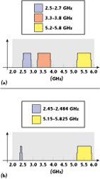
Several promising wideband antennas are suitable for applications in wireless local area network (WLAN) systems and worldwide interoperability for microwave access (WiMAX). Some monopole antennas for WLAN1,2 and WiMAX3,4 applications have recently been reported. Figure 1 shows the frequency allocations for WLAN and WiMAX.
There are many popular products for WLAN applications in the 2.4 and 5 GHz bands. The operating frequency bands of WiMAX are the 2.4, 3.5 and 5.2/5.8 GHz bands. For brevity, the low band denotes the band of 2.4 GHz (2.4 to 2.7 GHz); the middle band denotes the band of 3.5 GHz (3.3 to 3.8 GHz); and the high band denotes the band of 5.2/5.8 GHz (5.15 to 5.35 GHz/5.725 to 5.825 GHz). It is a standard for broadband wireless access at high speed, low cost and easy to deploy.
A theoretical 30-mile coverage radius and data rates up to 75 Mbps can be achieved with WiMAX technology. Throughput close to 1.5 Mbps, typical of broadband services,5–8 can also be obtained. The development of WiMAX technology is the immediate focus of the receiving industry.
Presently, the design of antennas for WLAN/WiMAX applications is an important issue. Because CPW-fed antennas have the advantages of wide bandwidth, simple structure, single metallic layer and easy integration with active devices or MMICs,9 they are good candidates for wireless communications antennas.
Some methods for WiMAX antenna design can be suggested. The design of a triple-band antenna with three resonant modes fitting the three bands of WLAN/WiMAX is not an easy task. A triple-band antenna has been reported,9 but is not suitable for WiMAX applications. Furthermore, the antenna design with three modes suffers from interference between the three resonant modes.10,11
Using a wideband/broadband antenna3,4 fits the requirements of WLAN/WiMAX antennas. In addition, some dual-band antennas covering the bands of WiMAX have been published.12 However, the low band is very near the middle band, which causes interference and coupling between the two bands of WiMAX. A triple-band polygonal slot antenna, using a dual-band rejection technique,13 has been constructed and investigated.

In this article, a novel design of a triple-band antenna is proposed, which evolved from a dual-band WiMAX antenna. For WLAN/WiMAX applications, the antenna bandwidth of the low band and high band should be enhanced. Bands I, II and III are defined as the band of 2.4 to 2.7 GHz, the band of 3.3 to 3.8 GHz and the band of 5.15 to 5.825 GHz, respectively.
The design of the antenna for WLAN/WiMAX follows the methods used in designing WiMAX antennas. First, a CPW-fed printed half-elliptic monopole antenna for broadband operation is constructed and investigated. Some specified parts of the half-elliptic monopole are then etched to obtain dual-band operation at 2.30 to 4.15 GHz and 4.93 to 5.83 GHz, and a novel design, for a CPW-fed antenna with dual-band operation for WLAN/WiMAX applications, is achieved.
In practical applications of WiMAX, the low band is close to the middle band, which leads to large coupling and interference effects. The wideband and dual-band antennas must use a filter to suppress this coupling, leading to increased cost. By etching a pair of slits in the proposed dual-band antenna, a rejected frequency band from 3 to 3.2 GHz is obtained and a novel design of a CPW-fed monopole antenna with three bands for WLAN/WiMAX applications is achieved. Good impedance matching and radiation characteristics of the constructed prototype are also shown.
Antenna Design
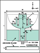
The geometry of the simple triple-frequency monopole antenna is shown in Figure 2, where the conductor is printed on a FR4 substrate of thickness h = 0.4 mm and dielectric constant εr = 4.4. A CPW transmission line, with a fixed signal-strip width Wf = 6 mm and a gap distance Ws = 0.5 mm between the strip and ground, is used to feed the antenna. Two finite ground patches of the same size (21 x 16.5 mm) are situated symmetrically on each side of the CPW line. The other antenna dimensions are: H = 2.8 mm, L = 53 mm, L1 = 6 mm, L2 = 19.7 mm, L3 = 12 mm, W = 33 mm, W1 = 11 mm, W2 = 2.5 mm, W3 = 4.5 mm, S = 1 mm and Ls = 15.5 mm.
Figure 3 illustrates the geometry of the proposed CPW-fed printed half-elliptic monopole antenna for WLAN/WiMAX operation in the 2 to 5.8 GHz bands. By properly tuning the dimensions L1 and W1, the CPW-fed printed wideband monopole, connected to the end of the CPW transmission line with a spacing H = 2.8 mm from the ground plane, a wideband antenna can successfully be created. The antenna dimensions are: h = 0.4 mm, L = 53 mm, W = 33 mm, L1 = 25.7 mm, W1 = 16 mm, Ws = 0.5 mm, Wf = 6 mm and S = 1 mm.
By etching some parts of the half-elliptic monopole antenna, as shown in Figure 4, a dual-band monopole antenna for WLAN/WiMAX can be achieved. Its dimensions are: h = 0.4 mm, H = 2.8 mm, L = 53 mm, L1 = 6 mm, L2 = 15.5 mm, L3 = 4.2 mm, W = 33 mm, W1 = 11 mm, W2 = 3.5 mm, W3 = 4.5 mm, Ws = 0.5 mm and Wf = 6 mm.
The dual bands cover the 2.30 to 4.15 GHz and 4.93 to 5.83 GHz bands. It is observed that the dual-band operation of the printed CPW-fed dual-band monopole antenna satisfies the requirements of WLAN/WiMAX operations. In practical applications of WiMAX, because the low band is close to the middle band, leading to large coupling effects and interference, a band-reject technique must be used to suppress these undesired effects.
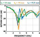
In order to reduce the interference, a band-reject function of the proposed antenna must be added to the dual-band monopole antenna. By etching one pair of slits (S x Ls mm) on the dual-band monopole antenna, a triple-band antenna for WLAN/WiMAX can be obtained. The slits determine the center frequency and bandwidth of the rejected-band.
The suppressed mode at 3 GHz is achieved by using a pair of slits whose length is approximately 15.5 mm (Ls = λg/4 = 15.25 mm at 3 GHz). For WiMAX applications, the optimal parameters of the proposed antenna were numerically obtained.
Experimental Results and Discussion

In this study, experimental results of impedance, radiation and gain characteristics of the proposed antenna are measured and presented. An HP 8753ES vector network analyzer was used for measurements of impedance characteristics. The NSI model FFC-600 far-field antenna measurement system permitted the measurements of radiation and gain characteristics of proposed antennas. The surface current distribution was analyzed using the commercial software tool HFSS.
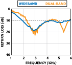
Figure 5 shows the measured return loss of the wideband printed half-elliptic monopole antenna. Its bandwidth (1.93 to 5.8 GHz) is approximately 100 percent. By etching two sections (yellow area) from the printed CPW-fed wideband antenna, the printed CPW-fed dual-band monopole antenna has been obtained and its return loss is also shown.
The impedance matching obtained (determined from a 10 dB return loss) of the proposed antenna can reach 2.30 to 4.15 GHz and 4.93 to 5.83 GHz. By choosing the proper dimensions of the slits etched on the dual-band monopole antenna, a tri-band for a WLAN/WiMAX antenna can be obtained (see Figure 6).
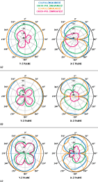
The antenna parameters have been given previously. A comparison of the simulated and measured return loss for the triple-band antenna is shown in Figure 7. The measured and simulated radiation patterns of the proposed printed CPW-fed dual-band antenna at 2.45, 3.5 and 5.5 GHz are shown in Figure 8.
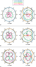
The measured and simulated radiation patterns of the proposed triple-band antenna at 2.5, 3.5 and 5.5 GHz are shown in Figure 9. The radiation patterns of the proposed antenna are well behaved. For comparison, the simulated surface current distribution at 3 GHz of the dual-band and the triple-band antennas are shown in Figure 10. It can be clearly seen that the current is concentrated at the edge of the two slits at 3 GHz. Therefore, the impedance mismatching and the gain drop at the rejected band is present in this design.
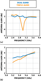
Figure 11 shows the measured antenna gain for the wideband operation of the half-elliptic monopole antenna. The gain of the half-elliptic antenna varies from 2.25 to 6 dBi within the 2.25 to 5.85 GHz band. Figure 12 compares the measured gains of the dual- and triple-band antenna.
A strong gain reduction in the rejected band near 3.2 GHz is shown for the WiMAX antenna. The antenna gain is between 1.68 and 2.39 dBi for the 2.5 to 2.7 GHz band of the WiMAX antenna; the antenna gain goes from 1.9 to 2.24 dBi for the 3.3 to 3.7 GHz band of the WiMAX antenna; and the antenna gain varies from 4.85 to 5.9 dBi for the 5.2 to 5.825 GHz band of the WiMAX antenna. The 2.5 to 2.7 GHz band of the WLAN/WiMAX antenna gain varies from 1.93 to 2.55 dBi; the 3.3 to 3.7 GHz band of the WLAN antenna is between 1.88 and 2.7 dBi; and the 5.2 to 5.8 GHz band of the WLAN antenna shows a gain from 5.1 to 5.61 dBi. Consequently, this antenna design is suitable for WLAN or WiMAX applications.
Conclusion
A novel printed CPW-fed monopole antenna, usable in WLAN and WiMAX applications, has been discussed and fabricated. This article focuses on a band-rejected design to fit WLAN/WiMAX operations. The band-rejected function is obtained by etching a pair of slits in the printed CPW-fed dual-band monopole antenna to reject frequencies from 3 to 3.22 GHz. This is needed to eliminate coupling, which occurs between the low and middle frequency bands and creates interference. The WLAN/ WiMAX antenna shown in this article eliminates the use of a filter and thus reduces the cost.
References
1. T.H. Kim and D.C. Park, “CPW-fed Compact Monopole Antenna for Dual-band WLAN Applications,” Electronic Letters, Vol. 41, 2005, pp. 291–293.
2. J.W. Wu. Y.D. Wang, H.M. Hsiao and J.H. Lu, “T-shaped Monopole Antenna with Shorted L-shaped Strip-sleeves for WLAN 2.4/5.8-GHz Operation,” Microwave and Optical Technology Letters, Vol. 46, 2005, pp. 65–69.
3. Y.T. Liu and K.L. Wong, “A Wideband Stubby Monopole Antenna and a GPS for WiMAX Mobile Phones with E911 Function,” Microwave and Optical Technology Letters, Vol. 46, 2005, pp. 485–487.
4. K.L. Wong, W.C. Su and F.S. Chang, “Wideband Internal Folded Planar Monopole Antenna for UMTS/WiMAX Folded-type Mobile Phone,” Microwave and Optical Technology Letters, Vol. 48, 2006, pp. 324–327.
5. “Deploying License-exempt WiMAX Solutions,” WiMAX White Papers, Intel Corp., 2005, http://www.intel.com/netcomms/ technologies/wimax/306013.pdf.
6. “Understanding Wi-Fi and WiMAX as Metro Access Solutions,” http://www.intel. com/netcomms/technologies/wimax/304471.pdf.
7. IEEE802.16 Working Group on Broadband Wireless Access Standards, http:// grouper.ieee.org/groups/802/16/index.html.

8. Worldwide Interoperability for Microwave Access Forum or WiMAX Forum, http:// www.wimaxforum.org.
9. W.C. Liu and C.C. Huang, “A CPW-fed L-shaped Slot Planar Monopole Antenna for Triple-band Operations,” Microwave and Optical Technology Letters, Vol. 44, 2005, pp. 510–512.
10. W.S. Lee, W.G. Lim and J.W. Yu, “Multiple Band-notched Planar Monopole Antenna for Multiband Wireless Systems,” IEEE Microwave and Wireless Component Letters, Vol. 15, 2005, pp. 576–578.
11. W.S. Lee, D.Z. Kim, K.J. Kim and J.W. Yu, “Wideband Planar Monopole Antenna With Dual Band-notched Characteristics,” IEEE Transactions on Microwave Theory and Techniques, Vol. 54, 2006, pp. 2800–2806.
12. C.Y. Pan, T.S. Horng, W.S. Chen and C.H. Huang, “Dual Wideband Printed Monopole Antenna for WLAN/WiMAX Applications,” IEEE Antennas and Wireless Propagation Letters, accepted for publication.
13. W.S. Chen and B.H. Kuo, “A Triple-band Polygonal Slot Antenna for WiMAX Applications,” Microwave Journal, Vol. 50, No. 1, January 2007, pp. 134–143.
Wen-Shan Chen received his BS degree in electronic engineering technology from the National Taiwan Institute of Technology (now known as the National Taiwan University of Technology) and his PhD degree from National Sun Yat-Sen University, Kaohsiung, Taiwan, ROC, in 2001. From 2001 to 2002, he was an assistant professor at the Chien-Kuo Institute of Technology, Changhua, Taiwan, ROC. He is currently an assistant professor in the department of electronic engineering at the Southern Taiwan University of Technology, Tainan, Taiwan, ROC. His research interests include antenna design, RF and microwave circuits.
Yu-Chen Chang received his BS degree from the Southern Taiwan University of Technology, Taiwan, ROC, in 2004, where he is currently pursuing his master’s degree. His main research interests include printed antenna for wireless communications, especially printed antennas for WiMAX applications.


