
Slot antennas have been investigated since at least the 1940s1 and are treated in many textbooks on electromagnetism. In these antennas, the feeding method generally uses a microstrip line crossing the center of the slot. However, this method increases the radiation resistance, which makes the impedance matching difficult.2 To solve this problem, Yoshimura3 and Pozar4 have proposed a second way, which offsets a short-circuited tuning stub and an open circuit-tuning stub at both ends of the slot.
Bi-directional slot antennas for broadband operation (30 to 90 percent) have been described.5,6 Unfortunately, these antennas have a low gain. A directional slot, backed by a ground plane, has shown higher gain than a bi-directional slot antenna, but the radiation pattern of a directional antenna has many nulls at higher frequencies, which restrict a wider application for wireless communications. Therefore, a technique to enhance the radiation of microstrip antennas has been proposed,7 although the narrow bandwidth of the antenna is still a major obstacle. An open slot structure has already been published;8 however, its major fault is a beam tilt and a narrow half-beam width at cellular, DCS, PCS, IMT-2000 and WLL frequencies.
In this article, a new structure for a printed, open slot antenna with dual reflectors is proposed. An open slot antenna is made by etching a rectangular slot in the ground plane of a microstrip. The proposed antenna uses a modified circular feed structure, which can provide a good impedance match for a wide slot. Moreover, the dual reflectors (reflectors 1 and 2) lead to an enhanced beam tilt angle and half-power beam width of the E-plane pattern in each frequency band. This antenna also shows wide-band and high gain characteristics.
Antenna Structure and Experimental Results
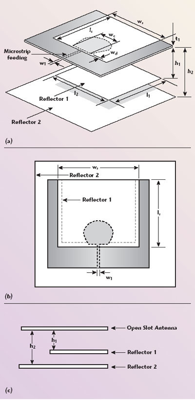
The geometry of the proposed circular-fed, open slot antenna with dual reflectors for dual- and wide-band operation is shown in Figure 1. The open slot antenna is etched in the ground plane on the substrate FR-4 (?r = 4.3) with a thickness t1 = 1.6 mm. The open slot antenna has a slot width ws and a length ls, chosen to improve bandwidth, and the top of the slot is opened to reduce the radiation tilt angle in the E-plane for practical applications. The microstrip line width w1 is designed for a 50 ? input impedance. The modified circular microstrip feed line is used as a feeding method to match easily to the wide slot. The reflectors 1 and 2 are positioned with height h1 and h2 from the back of the open slot antenna. Reflector 1 is used for the upper band impedance matching and directional pattern; Reflector 2 is used for enhancing the beam tilt angle and providing an increment in the half-power beam width in the E-plane pattern. Figure 2 shows a photo of the fabricated antenna. The reflectors are made of aluminum plates and the antenna is fed through a coaxial cable and a 50 ? SMA connector. The fabricated antenna dimensions are ls = 120 mm, ws = 132 mm, wc = 32 mm, wd = 2.5 mm, h1 = 28 mm and h2 = 45 mm. The low frequency band is affected by ls, ws and h2. The upper band is affected by wc, wd and h1. The overall size of the proposed antenna is 180 mm × 160 mm × 47.6 mm. The VSWR of the proposed antenna was measured with an HP8753 ES network analyzer. The far-field radiation patterns were measured in an anechoic chamber.

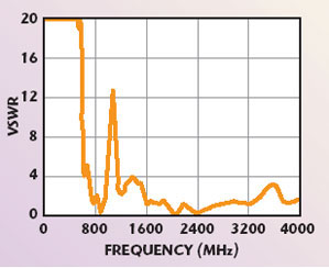
The measured VSWR data of the proposed antenna is shown in Figure 3. The measured bandwidth is 755 to 968 MHz in the lower band and 1574 to 3389 MHz in the upper band. The VSWR = 2 bandwidth is approximately 24.7 percent at the lower band and 73.1 percent at the upper band. The proposed antenna shows its dual-band and wide-band characteristics. After calibration, the far-field radiation patterns were measured using a horn antenna. Figure 4 shows the H-plane and E-plane radiation patterns at the lower band. Figure 5 shows the H-plane and E-plane radiation patterns at the upper band. Table 1 shows the measured characteristics (gain, beam tilt angle and half-power beam width (HPBW) of the E-plane) of the proposed antenna. This antenna reduces the beam tilt angle of the E-plane for practical applications such as DCS, PCS, IMT-2000 and DMB. The measured maximum gain is 9.51 dBi at 0.96 GHz and 8.46 dBi at 2.2 GHz, respectively.
The measured gain versus frequency for the cellular and GSM bands is shown in Figure 6. The gain is relatively high over most of the band, which is most probably due to the effect of the finite size of the antenna substrate, that is the power in the surface wave is not confined to the substrate but diffracted by the substrate edge, an effect which was not taken into account in the analysis. The measured gain is 5 dBi over the entire usable frequency band, but drops off rapidly past the band edges. The measured gain versus frequency for the PCS, IMT-2000 and WLL bands is shown in Figure 7. The measured gain is also 5 dBi over the entire band in the usable frequency band, but drops off rapidly past the band edges. This is due to impedance mismatch and pattern degradation, as the back radiation level increases rapidly at these frequencies.
Conclusion
In this article, a modified, circular-fed, open slot antenna with dual reflectors is proposed. The measured bandwidth of the proposed antenna is approximately 24.7 percent at the lower band and 73.1 percent at the upper band for a VSWR £=2.0. The experimental results of this antenna showed a multi-band and a high gain characteristic. The proposed antenna offers a reduced beam tilt angle of the E-plane pattern for practical applications such as cellular, GSM, PCS, IMT-2000 and WLL.
References
1. H.G. Booker, “Slot Aerials and Their Relation to Complementary Wire Aerials,” Journal of the IEE (London), Part IIIA, Vol. 93, 1946, pp. 620–626.
2. R. Garg, P. Bhartia, I. Bahl and A. Ittipiboon, Microstrip Antenna Design Handbook, Artech House Inc., Norwood, MA, p. 442.
3. Y. Yoshimura, “A Microstripline Slot Antenna,” IEEE Transactions on Microwave Theory and Techniques, Vol. 20, No. 11, November 1972, pp. 760–762.
4. D.M. Pozar, “Reciprocity Method of Analysis for Printed Slot and Slot Coupled Microstrip Antennas,” IEEE Transactions on Antennas and Propagation, Vol. 34, No. 12, December 1986, pp. 1439–1446.
5. Y.W. Jang, J.C. Chai and H.S. Shin “A Large Bandwidth T-shaped Microstrip-fed Ground Plane Slot Antenna,” Microwave Journal, Vol. 45, No. 1, January 2002, pp. 503–507.
6. Y.W. Jang, “Experimental Study of Large Bandwidth Three-offset Microstripline-fed Slot Antenna,” IEEE Microwave and Wireless Components Letters, Vol. 11, No. 10, 2002, pp. 425–427.
7. A.K. Bhattacharyya, “Effects of Finite Ground Plane on the Radiation Pattern Characteristics of a Circular Patch Antenna,” IEEE Transactions on Antennas and Propagation, Vol. 38, 1990, pp. 152–159.
8. H.C. Go and C.Y. Lee. “A New Open Slot Antenna for Wide and Dual-band Operations,” 2003 Asia-Pacific Microwave Conference Digest, Vol. 3, pp. 1864–1867.