The emerging ultra-wideband (UWB) radio is the technology for transmitting and receiving short, information-encoded, electromagnetic impulses.1,2 UWB technology is loosely defined as any wireless transmission scheme that occupies a bandwidth of more than 25 percent of a center frequency, or more than 1.5 GHz. According to the Federal Communications Commission (FCC),3 the frequency band of UWB (the category of communications and measurement systems) should be contained between 3.1 and 10.6 GHz. Figure 1 shows the spectrum allocation of the current UWB system for multi-band OFDM (MBOA) and direct sequence (DS) CDMA UWB. The MBOA has four groups (group A, B, C and D) and thirteen bands, each with a bandwidth of 500 MHz. The DS-UWB system has a low band from 3.1 to 5.15 GHz and a high band from 6 to 10.1 GHz. Due to its extremely wide operating bandwidth, it could possibly interfere with other existing electronic systems operating at the same time. In order to make it compatible with existing narrow-band radio services, the maximum permissible effective isotropic radiated power (EIRP) density is set as –41.3 dBm/MHz.3 Hence, the emission limits of the radiated power are a critical consideration in UWB radio systems, especially for the antenna design.
In general, there are two ways to limit the radiated PSD shaping to conform to the standard mask set by the FCC:4 the first is to design the antenna as a special filter to suppress the unwanted radiation outside the UWB band or, second, to select a source pulse in the specific band to let the radiated PSD meet the FCC required emission limits. In this article, the second approach is used. Here, a printed monopole-type antenna is adopted for the design of a broadband antenna for UWB application.5,6 The design simulation, fabrication and measurements of a printed planar triangular monopole antenna (PTMA), fabricated on a FR-4 PCB, are reported. The HFSS 3-D EM simulator is employed for design simulation. The antenna input VSWR, the phase of the input impedance and the radiation patterns are presented. Also, an FDTD code, developed with the Kirchhoff’s surface integral representation (KSIR), is used to compute the time-domain far-field distribution. This is to investigate the radiated PSD shaping to comply with the FCC emission limit mask. First-order Rayleigh pulses with ? = 20, 30 and 50 ps are used and the resulting PSD are compared.
Antenna Design
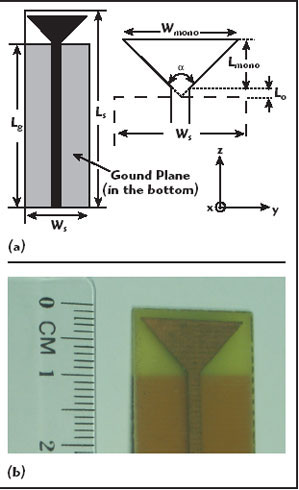
In this article, a printed PTMA is developed, based on a triangular monopole antenna.5,6 The structure of this antenna consists of a tapered radiating element excited by a suitable feed-structure, such as a coplanar waveguide (CPW) or microstrip line. As shown in Figure 2, the antenna geometry, the width, length and flare angle of the antenna are denoted by Wmono, Lmono and a, respectively. A 50 ? microstrip line is used to feed the PTMA at the apex angle of the triangular patch. The distance between the end of the monopole and the terminal of the microstrip line is denoted by L0. The antenna is printed on one side of a FR-4 substrate with a width Ws, a length Ls and a thickness T. On the other side of the substrate, a ground plane of width Ws and length Lg is printed. The detailed parameters of the antenna are summarized in Table 1. The figure also shows the photograph of a printed PTMA fabricated on a FR-4 substrate.
Measurement Results
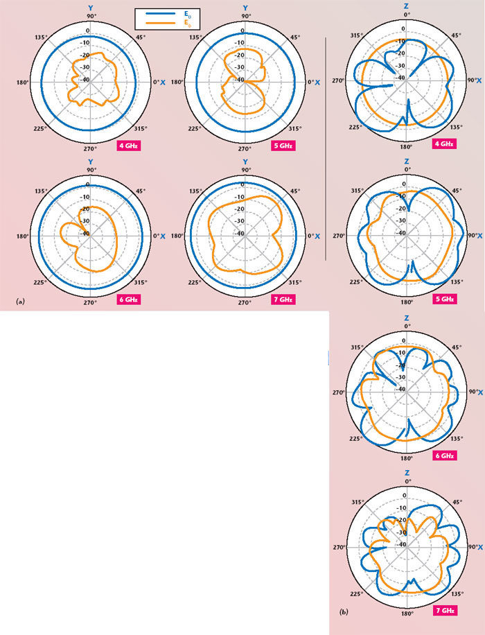
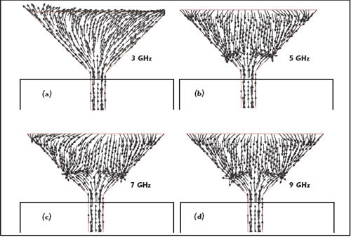
The HFSS-simulated current distributions of the printed PTMA at 3, 5, 7 and 9 GHz are shown in Figure 3. The simulation shows that the currents of the PTMA are almost distributed along the same directions (z-axis), which is similar to the behavior of a monopole antenna. Figure 4 shows the measured antenna input VSWR and the phase of the input impedance from 3 to 10 GHz. The measured input VSWR is less than 2.5 from 4 to 10 GHz and the measured phase distribution of the input impedance is also quite linear except in the frequency range from 5 to 6 GHz. The measured representative H-plane (xy-plane, ? = 90°) and E-plane (xz-plane, ? = 0°) antenna patterns at 4, 5, 6 and 7 GHz are shown in Figure 5. It can be seen that the H-plane patterns are all quite omni-directional.
Radiated Power Spectrum Density (PSD)
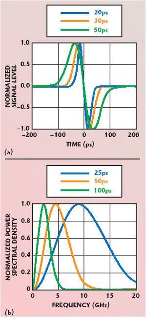
For the conventional narrow-band antenna design, the frequency-domain information is more useful and significant than the one in the time domain. For a UWB radio system excited with a short pulse, the study of temporal properties will be helpful in designing and analyzing the UWB antenna. The desired time-domain information can be readily obtained by using time-domain numerical methods, such as the finite-difference time-domain (FDTD) method. However, since the FDTD method is inherently a near-field technique, a time-domain near- to far-field transformation is employed to efficiently compute the far-field antenna parameters.7,8 Ultimately, the frequency-domain response can be obtained with the fast Fourier transform (FFT). The effect of various source pulses on the radiated PSD shaping are then studied by using the first-order Rayleigh pulses, which are differentiated Gaussian pulses. The parameter ? is used to describe the time duration when the normalized single level, v0(? ), of the source pulse equals to e-1. The first-order Rayleigh pulses with ? = 20, 30 and 50 ps are used in the FDTD computation. It is noted that the first-order Rayleigh pulses with ? > 60 ps are not considered here because their corresponding spectra of 10 dB bandwidths do not fully occupy the desired 7.5 GHz bandwidth for UWB communication. Figure 6 shows the time-domain and frequency-domain waveforms of these first-order Rayleigh pulses. Unlike the Gaussian pulse, these Rayleigh pulses are monocycle pulses in the time domain and do not generate any direct current (DC) component in the frequency domain. For UWB antenna design, the transfer function of the antenna is important both to comply with the FCC power emission limits and to preserve the transmitted waveform information. The transfer function of an antenna is defined as the ratio of radiated electric fields in the frequency domain and the spectrum of a source signal (voltage) at the transmitting antenna.4 For the FDTD calculation, the transfer functions of the antenna can be obtained by applying the definition. For measurement, the transfer functions can be derived from the transmission scattering parameters, S21, the input impedance and the antenna gain.9 The measured transfer functions of the printed PTMA at F = 0°, 90°, 180° and 270° in the H-plane are plotted in Figure 7. Due to the instrument’s limitations in the anechoic chamber, only the frequency band from 3 to 8 GHz is presented. A good agreement among transfer functions at F = 0°, 90°, 180° and 270° is observed because of the omni-directional radiation pattern of the printed PTMA in the H-plane. The magnitudes of the transfer functions are close to a flat response over the interested frequency band. From the signal point of view, this PTMA antenna is a bandpass filter with nearly constant magnitude. Hence, the desired radiated PSD of the printed PTMA can be achieved readily once the source pulses have been properly evaluated. Figure 8 shows the computed radiated PSD of the printed PTMA excited by the first-order Rayleigh pulses with ? = 20, 30 and 50 ps. The co-polarized component of the printed PTMA, Eq, in the direction of q = 90° is computed at the distance of r = 2 m. All the computed results of PSD are normalized to –41.3 dBm/MHz. In comparison with the FCC’s indoor and outdoor masks, it is found that the radiated PSD of the first-order Rayleigh pulses with ? = 20, 30 and 50 ps all comply with the FCC’s indoor and outdoor mask from 2 to 10.6 GHz. Beyond 10.6 GHz, however, only the pulse with ? = 50 ps can comply with the FCC’s indoor and outdoor masks.
Conclusion
This article presents a PTMA for UWB communication. The HFSS 3-D EM simulator is employed for design simulation. The printed PTMA is fabricated on a FR-4 PCB substrate. The measured VSWR is less than 3 from 4 to 10 GHz. The measured phase distribution of the input impedance is quite linear (except in the frequency range from 5 to 6 GHz). The H-plane patterns are almost omni-directional in the UWB frequency band. The antenna transfer functions at F = 0°, 90°, 180° and 270° in the H-plane are measured and a nearly flat response can be observed. The KSIR is used in the developed FDTD code to compute the time-domain far-field distribution. This is to investigate the PSD shaping to comply with the FCC emission limit mask. The effect of different source pulses (first-order Rayleigh pulses with ? = 25, 50 and 100 ps) on the radiated PSD shaping is studied. Due to the flat response of the antenna transfer function, the desired radiated PSD of the printed PTMA can be readily achieved with a proper source pulse. It is found that only the radiated PSD of the first-order Rayleigh pulse with s = 50 ps can comply with the FCC’s indoor mask above 2 GHz. As for the outdoor mask, the same pulse can comply with the FCC emission limit.

References
1. K. Siwiak and D. McKeown, Ultra-wideband Radio Technology, John Wiley & Sons Inc., UK, 2004.
2. S. Roy, J.R. Foerster, V.S. Somayazulu and D.G. Leeper, “Ultra-wideband Radio Design: The Promise of High Speed, Short-range Wireless Connectivity,” Proceedings of the IEEE, Vol. 92, February 2004, pp. 295–311.
3. US 47 CFR Part 15 Ultra-wideband Operation FCC Report and Order, 22 April 2002.
4. Z.N. Chen, X.H. Wu, H.F. Li, N. Yang and M. Chia, “Considerations for Source Pulses and Antennas in UWB Radio System,” IEEE Transactions on Antennas and Propagation, Vol. 52, July 2004, pp. 1739–1748.
5. J.M. Johnson and Y. Rahmat-Samii, “The Tab Monopole,” IEEE Transactions on Antennas and Propagation, Vol. 45, January 1997, pp. 187–188.
6. H.M. Chan, “Microstrip-fed Dual Frequency Printed Triangular Monopole,” Electronics Letters, Vol. 38, June 2002, pp. 619–620.
7. A. Taflove, Advances in Computational Electromagnetics, Artech House Inc., Norwood, MA, 1998.
8. O.M. Ramahi, “Near- and Far-field Calculations in FDTD Simulations Using Kirchhoff’s Surface Integral Representation,” IEEE Transactions on Antennas and Propagation, Vol. 45, May 1997, pp. 753–759.
9. T.G. Ma and S.K. Jeng, “Planar Miniature Tapered-slot-fed Annular Slot Antennas for Ultra-wideband Radios,” IEEE Transactions on Antennas and Propagation, Vol. 53, March 2005, pp. 1194–1202.