
Communications at mmW frequencies offers several unique and very potent advantages as well as some sizable disadvantages. In order to develop cost-effective, high performance links a solid understanding of the issues and in particular how to benefit from the advantages while mitigating the disadvantages is crucial.
Reduced hardware size and wider bandwidths are among the leading advantages for radios operating at mmW frequencies. For instance, mmW radios utilize smaller high gain antennas, waveguide and RF front ends than do their lower frequency counterparts. Reasonably priced mmW MMICs are readily available for all small-signal active functions—LNAs, mixers, LO multipliers, etc. The availability of very wide, contiguous bandwidth (7 GHz in V-band, two 5 GHz bands in E-band) allows low cost modulation/demodulation architectures for multi-gigabit data rates.
These advantages are somewhat offset by several disadvantages at mmW, including a higher attenuation vs. precipitation rate (rain, snow and hail) in comparison to lower frequency radios having the same Tx power and Tx/Rx antenna gain product. Lower frequency radios often address their lower gain antennas by using higher power amplifiers in the transmitter.
Unfortunately, high power amplifiers are very expensive at mmW frequencies, thereby limiting their use as a practical solution. Some factors are “wild cards” in terms of being advantages or disadvantages. For instance, the high atmospheric attenuation peak centered at 60 GHz (≈16 dB/km at sea level and dropping to ≈5 dB/km at 4 km above sea level) would seemingly discourage use, but is actually a benefit to secure military systems and has therefore been utilized for decades.
Additional considerations relate to unlicensed versus registered bands. Unlicensed radios (FCC 15.255 compliant radios operating in the 57 to 64 GHz band, for example) can be deployed/re-deployed wherever/ whenever desired, without government coordination. Registered radios (that is, those in the 71 to 76, 81 to 86 GHz band) must pass an interference analysis for a specified installation site as part of the FCC registration process; a fee must be paid. (Government agencies register their links with the NTIA.) Registration provides some protection from an interfering radio in the future.
High Quality Links
Successful communication necessitates reception of a high quality signal despite the presence of adverse conditions like inclement weather, platform movement, extraneous signals (multipath and EMI, for example) and perhaps even denial-of-service attacks. Quality is typically quantified by bit error rate (BER); the maximum acceptable BER is usually established by the signal use (voice, video, or data). For example, voice communication might require a maximum BER of 1x10⁻³ or 1000 ppm, whereas video and gigabit Ethernet might require maximum BERs of 1x10⁻⁸ and 1x10-12, respectively.
Ideally, BER is a function only of the signal-to-noise ratio (S/N) for a given radio modulation type (OOK, BPK, QPSK, or QAM). For example, a BER = 1x 10-12 for OOK requires a received S/N ≈15.3 dB; a higher S/N results in a lower BER until a residual minimum level is reached. Therefore, successful communication boils down to achieving the necessary S/N. For most installations, this ultimately requires successful navigation through a minefield of non-RF issues like modeling the weather, or maintaining boresight alignment in spite of a platform in constant motion, perhaps by utilizing a combination of global positioning, inertial navigation, or video alignment systems controlling a positioner.
The Communications Link Equation
The link S/N = Pr – Nein
where
Pr = received signal
Nein = receiver equivalent input noise
The received signal =
Pr = Pt Gt Gr λ2 L/(4πR)2
where
Pt = transmitted signal power
Gt = transmit antenna gain
Gr = receive antenna gain
λ = carrier wavelength
L = oss factor (includes losses due to the weather, polarization or bore-sight alignment errors, etc.)
R = distance between the antennas
The receiver equivalent input noise =
Nein(dBm) = kTBWnF
where
k = Boltzmann’s constant
(1.38 x 10⁻²³ J/K)
T = temperature (K)
BWn = receiver noise bandwidth
F = noise factor (note that noise figure =10 log F)

As an example consider a Gigabit Ethernet 71 to 76 GHz (E-band) radio with Pt = 10 dBm, 2ft. dia. antennas (Gt = Gr = 50 dBi), operating under clear air weather conditions, with no bore-sight or polarization errors, 1.88 GHz detection noise bandwidth and 8 dB noise figure, using OOK modulation.
This radio will require 15.3 dB S/N to achieve 1x10-12 BER and will therefore have a maximum theoretical operating distance of Rmax, approximately equal to 22 km (see Figure 1).
In 100 m-visibility fog, or uniformly distributed rain falling at the rates of 5 mm/Hr (medium), 25 mm/Hr (heavy), or 100 mm/Hr (very heavy), Rmax drops to ≈17, 6.4, 2.6 and 1.1 km, respectively.
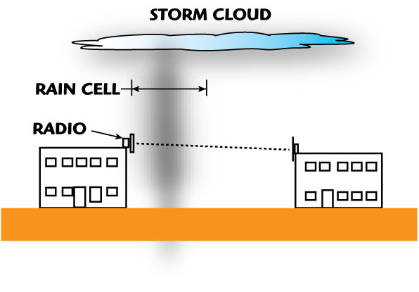
To complicate matters, high rain rates are generally localized events (rain cells) with varying sizes (inversely proportional to rain rate) that result in varying attenuation along the link path, hence the probable need to develop a rain attenuation model for long (vs. rain cell size) link paths.
Atmospheric Propagation Losses
It is obvious from the figure that propagation losses due to the various weather conditions can dramatically impact operating range.
In the communications link equation, the sum total of all the propagation losses (from “clear air” plus the effects of rain, snow, etc., when applicable) are lumped into L for calculation of the received power.
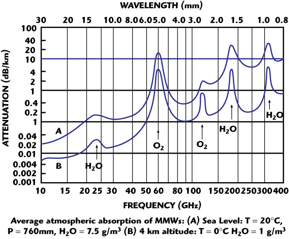
Except for 60 GHz, the common radio frequencies (27, 38, 74, 84 and 94 GHz) appear in atmospheric windows for minimum propagation losses. As mentioned earlier, the relatively opaque region at 60 GHz at low altitudes has been exploited for military satellite-to-satellite communications for decades since it provides eavesdrop and jam-proof protection from terrestrial terminals. Since these propagation losses are critical to developing a successful link, they are quantified below in more detail.

Figure 2 shows the clear air atmospheric attenuation from 10 to 400 GHz at both sea level (top curve) and at 4 km above sea level.
In particular, note the high attenuation peaks at 60 GHz (≈16 dB/km at sea level; ≈5 dB/km at 4 km) and the windows from < 71 to > 86 GHz (≈0.5 dB/km at sea level; < 0.2 dB/km at 4 km above sea level).
These attenuation levels are significantly higher than those in the 27 and 38 GHz bands.
Figure 3 details the attenuation from 50 to 70 GHz, revealing the greater than 30 oxygen molecule resonances which become increasingly distinct at higher altitudes; this is a consequence of the oxygen molecule having a magnetic moment due to an unpaired electron spin, and the loss of energy (due to electron-spin realignment) by an RF field propagating through it.

Under higher pressure conditions (which exist at lower altitudes), collisional broadening increases, the resonance lines smear together, and a relatively wide and smooth attenuation characteristic results, centered at 60 GHz.
Table 1 details the operating distances of identically configured 60 GHz (V-band) and 71 to 76 GHz (E-band) radios under various weather conditions.
Note that in clear air at sea level, the atmospheric attenuation due to oxygen drastically reduces the operating distance of the V-band radio; also note that operating distances become comparable in very heavy rain, where attenuation due to rain predominates.
If low probability of intercept and/or resistance to jamming are paramount, the attenuation due to oxygen can be beneficial. The extent to how secure communications at 60 GHz can be is illustrated in Figure 4.
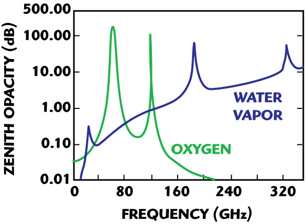
The total attenuation through the atmosphere looking towards the zenith (that is, straight up) is > 200 dB, and the attenuation looking towards the horizon is even higher.
For this reason eavesdropping or denial-of-service attacks of a satellite-to-satellite communications link from a land-based terminal is virtually impossible.
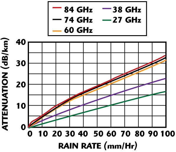
Figure 5 details the attenuation due to rain rate. Caution should be exercised when calculating path attenuation due to high rain rates since these events become highly localized for increasing rates (see also Figure 6, which details rain cell diameter vs. rain rate).
If the entire link path is not within the rain cell, then the calculated losses will be too high.
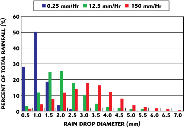
For example, according to Figure 1, the maximum link distance for a uniform 5 mm/Hr rain rate is 6.4 km, but Figure 7 shows that the rain cell diameter for a 5 mm/Hr rain rate is typically less than 3 km as defined by the distance where the rain rate has dropped by 50 percent.
Given the diversity of rain rate over a relatively short distance (well within the range of many communication links), the uncertainty in path loss is considerable.
Raindrops are not uniform for a given rain rate, but instead have a rather broad distribution, as is evident in Figure 7.
This further complicates the loss calculations. This distribution is considered responsible for the discrepancy between the theoretically predicted attenuation resonance at mmW frequencies and the observed attenuation resonance.
Note the theoretical resonance would occur when the circumference of the raindrop is equal to the wavelength.

Very little published data exists for attenuation due to snow, but it is generally accepted that light, dry snow has about 10 dB less attenuation than rain at the same rate of precipitation, and that the attenuation due to heavy, wet snow approaches that of rain with the same rate of precipitation, due to the high water content.
The attenuation from small diameter hail, since it is composed almost entirely of ice, would be expected to be about the same as that from rain with the same rate of precipitation.
Case Studies
Developing the optimum link frequently requires a trade-off of various parameters. Insight into optimum design choices can usually be gained by reviewing relevant case studies with an eye toward the network challenges and the solutions employed.
Towards that end, two radically different case studies are considered.
Case Study 1:
Airborne Surveillance Video Down-link
The installation depicted in Figure 8 required a very high data rate (> 1 Gbps) video down-link from an airborne platform.
The high data rate is required to support the transmission of data from a very high resolution camera along with a high frame update rate to eliminate “blind time.” Additionally, the cruising altitude must be sufficiently high in order to ensure pilot safety (avoiding enemy fire) in a dry environment (that is, no significant rain).
The airborne environment requires antennas with high gain to maximize the operating distance, as well as small size to fit within the gimbaled yoke.
The airborne terminal is gimbaled for tracking over a very wide arc because of the circular flight path. Unfortunately, the very narrow antenna beamwidth (less than a degree) initially challenged the beam-pointing accuracy of the stabilized platform.
While the airplane cruises at sufficiently high altitude for safety from a variety of weapons, it is not high enough to preclude buffeting from wind or pressure gradients.
So, while the flight is fairly smooth overall, there are intermittent bumps, which the gimbaled radio mount must be able to compensate for. Ideally, the beam-pointing error would be only a small fraction of the antenna’s –3 dB beamwidth to minimize signal loss or amplitude modulation.
Unlike the airborne radio terminal, the ground-based terminal presents much less tracking challenge because the radius of the circular flight path is much less than the link distance.
This particular installation illustrates some thorny antenna trade-offs, namely:
• The need for higher gain to guarantee sufficient stand-off distance, in spite of the fact that higher antenna gain results in narrower beamwidth
• The desire for a wide beamwidth (thereby reducing gain) to reduce the pointing accuracy demands on the airborne gimbaled mount and its control loop complexity
• The desire for smaller antenna/radio size/weight for the airborne platform Because of the non-negotiable requirement for very high data rate and small size, a mmW radio with its advantage in size and bandwidth was the clear choice.
Case Study 2:
Enterprise Installation
The second case study considers an installation that typifies the most common use of mmW point-to-point radio links. These are wireless extensions of high data rate communications from existing fiber-fed buildings to other buildings, eliminating the need to “pull” building permits and dig trenches across parking lots or erect poles (see Figure 9).

As shown previously, the link S/N is calculated to determine if the required BER can be achieved with the anticipated weather conditions (for the continental US, FCC OET Bulletin 70 provides a Crane map showing the maximum rain rates for various system availability times; ITU rain charts are available for other countries). GigaLink® radio availability for various standard data rates are detailed in Table 2.
One of the biggest issues affecting the viability of a link using high gain/narrow beamwidth antennas is the need for mount stability. The widest beamwidth accepted by the FCC for an E-band antenna is approximately 1°. Many E-band radios use antennas with approximately 0.5° beamwidth. For such narrow beamwidths, it is critical that the transmitting and receiving antennas maintain their locations relative to each other. In other words, the structure that the antenna is mounted to must exhibit enough stability to maintain the antenna’s position within a small fraction of the antenna beamwidth.
Accommodating 0.5° beamwidth antennas is routinely achieved when mounting to the relatively short masonry/steel buildings typically found in office parks. However, modern high-rise buildings are often designed to sway when stressed from high winds or earthquakes. This is clearly problematic for narrow beam antennas. Radios based on top of these structures might only accommodate wider beamwidth antennas or the antennas may need to be mounted below mid-height where structure sway is within acceptable levels.
Cost vs. Performance Trade-offs
For most installations, the type of payload (voice, video, or data) determines the required BER. For example, voice might require a BER = 1x 10⁻³, while Ethernet might require a BER = 1 x 10-12. Other considerations for quality of service include the operating distance, the propagation losses (note: the rain rate which is used to calculate the propagation loss is determined from a Crane rain map and the required system up time) and the preference for unlicensed use or registered use, thereby leading to different operating bands: 57 to 64 GHz vs. 71 to 76/81 to 86 GHz.
Often, the only “choices” available to increase performance and/or extend operating distance include increasing the transmitter power level, increasing the antenna size (which increases the gain while narrowing the beamwidth) and/or reducing the receiver noise figure.
In general, if a narrower beamwidth is not a problem, it is much less expensive to use a higher gain antenna to increase range than it is to increase the transmitter power. For example, increasing the antenna size from 1 ft. dia. to 2 ft. dia. increases the S/N by 12 dB for relatively little additional cost as compared to increasing the transmitter power by 12 dB. Unfortunately, only 1 ft. and 2 ft. diameter antennas are presently available at reasonable cost. Because the receiver noise figure can only be marginally improved at very high cost, this option is limited.
Fortunately, innovation and market drive will help drive down the cost of these mmW systems. For example, the first FCC 15.255 certified (unlicensed use), 60 GHz 1.25 Gbps radios were introduced by Terabeam/ HXI in 2003. Today the cost for that product with improved performance is approximately 67 percent less. This is the result of increased sales due to the market’s appetite for low cost, high data rate wireless products. Additionally, the allocation by the FCC of an additional 10 GHz of bandwidth in E-band, combined with much higher allowable EIRP levels than at 60 GHz and the protection provided by link registration, allows longer distance solutions for high bandwidth needs.
Conclusion
While millimeter-wave radios must overcome a number of environmental challenges ranging from adverse weather conditions to unstable mounting surfaces, they do offer considerable benefits in terms of available bandwidth and relative size. This bandwidth capacity is ideal for addressing a number of hot applications. While the original need for multi-gigabit, wireless last-mile connectivity still exists, a new need for multi-gigabit wireless connectivity providing mobile high definition video is growing. This need is shared by both military (surveillance) and commercial (HDTV) sectors. Driven by this growing market demand and made possible through innovative engineering, mmW-based point-to-point and point-to-multipoint networks will continue to deliver more wireless bandwidth for less.
References
1. Federal Communications Commission, FCC OET Bulletin 70, Millimeter-wave Propagation: Spectrum Management Implications.
2. Federal Communications Commission, FCC 05-45 Memorandum Opinion and Order, released March 3, 2005.
3. N.C. Currie and C.E. Brown, Principles and Applications of Millimeter-wave Radar, Artech House, Norwood, MA.
4. Wireless Communications Association International, Path Coordination Guide for the 71–76 and 81–86 GHz Millimeter-wave Bands, Doc.: WCA-PCG-7080.