
The development of multiple beams and reconfigurable antennas has always been tightly connected to that of beam-forming networks. The beam-forming network (BFN) is often the dominant component, the true “heart” of most multiple beams antennas.

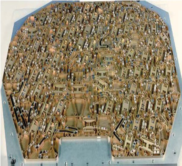
Beam-forming networks are complex networks used to precisely control the phase and amplitude of radio frequency (RF) energy passing through them, which is conveyed to the radiating elements of an antenna array. An example of a 20 GHz BFN developed by Selenia1 (now Thales Alenia Space) for the European Space Agency (ESA) ASTP Program, circa 1982, is shown in Figure 1. BFN configurations vary widely from just a few basic building blocks, up to tens of thousands of them depending on system performance requirements.
A “fixed” BFN generates a time invariant set of spot beams of different shapes; in one such network, amplitude and phase coefficients are fixed at the time of design. A “reconfigurable” BFN allows on-orbit control of amplitude and/or phase excitation coefficients; this type of network, generating M beams and interfacing N radiating feeds, will need M x N control elements (variable phase shifters and variable attenuators).
As far as passive BFNs are concerned, the choice of the transmission line technology depends on several parameters, such as operating frequency, bandwidth, power handling requirement, possibility of passive intermodulations and/or of multi-pactoring. At frequencies below C-band, TEM transmission lines are usually adopted (that is stripline, suspended microstrip and square coaxial line). The state-of-the-art of the TEM BFN technology is that of multi-layer, case-less microwave circuit design with inter-layer connections. The three-dimensional nature of the multi-layer approach allows flexibility in packaging topography as well as in the location of input and output ports. Utilizing a lamination process in autoclaves under high pressure and high temperature conditions, the multi-layer stack of “soft” material substrates is fused into a solid, high integrity assembly. At Ku-band and higher frequencies, waveguide BFNs are more often selected. In active phased-array antennas, beam-forming networks operating at IF frequencies have also been realized. The trade-off (in terms of mass, power consumption and overall complexity) between realizing the beam formation at RF or IF frequencies depends on the actual number N of array elements and the actual number M of beams to be generated. The adoption of digital signal processing architectures led to multiple beam antennas based on digital beam-forming (DBF) techniques. Such techniques allow the implementation of phased-array antennas (both in a Direct Radiating Array or in an Array-fed Reflector configuration) with full control of their potential capabilities, such as beam steering and shaping, interference rejection and nulling. A dedicated section needs to be devoted to the developments of Butler matrices and other beam-forming components for semi-active antennas, based on the multi-port amplifier concept. The aim of this article is to present a concise but systematic summary of the most important BFN principles and technologies. In doing that, the article will also describe the major developments performed in Europe on the subject.
A Proposal for a Beam-forming Network Classification

At present, a widely agreed and systematic classification for beam-forming networks does not exist. On the contrary, contradictory terminologies are quite often used, depending on the antenna systems in which the BFNs are included. A frequent confusion is generated by the indiscriminate application of the terms “passive” and “active” to both antennas and BFNs. An antenna is named “active” when each independently controlled radiating element (individual feed or subarray) is directly connected to the receive low noise amplifiers (LNA) or transmit power amplifiers (PA) amplifying modules. An active array antenna is usually a multiple beam antenna, but not necessarily reconfigurable or adaptive. On the other hand, many passive antennas exist that are reconfigurable and adaptive.
Figure 2 shows a schematic of a reconfigurable BFN in a passive antenna and an L-band electronically despuned antenna of Meteosat Second Generation from Thales Alenia Space.2,3 It is therefore proposed to classify the beam-forming networks depending on their ability to generate steerable, reconfigurable or adaptive beams. Two main categories can be then identified: “fixed” (static) BFNs and “reconfigurable” (agile) BFNs. The main difference between a “reconfigurable” BFN with respect to a “fixed” one is the need for variable components: switches, variable attenuators, variable phase shifters and variable power dividers (VPD). The type of reconfigurability required, whether fast or slow, will drive the selection of the technology (electromechanical components, for instance, rather than fast-switching MMIC devices). All components in a BFN, both fixed (such as hybrid couplers, power splitters or transmission lines) and variable, will be equally affected by the passive or active nature of the antenna system they belong to. In beam-forming networks for passive antennas, power handling and losses are a major concern; this confines the available design options to a restricted number. In active antennas, where losses in the BFN are not a primary problem, a much wider range of technologies and techniques is available, leading to very lightweight and compact designs. From a technical viewpoint, beam-forming networks have been classified into four main families:

• Analog BFNs (either operating at RF or at IF frequencies)
• Spatial BFNs (such as lens antennas, reflective arrays, etc.)
• Digital BFNs, operating in the digital domain after an analog-to- digital conversion
• Optical BFNs, where optical techniques are applied to microwave modulated optical carriers.
Beam-forming Network Topologies
The fundamental problem in the design of any beam-forming network is that of achieving, at the N outputs of an RF network, a desired distribution of amplitudes and phases (excitation coefficients), in order to properly feed a corresponding number of radiating elements and obtain the required far-field composite pattern. It is evident from this definition that the basic components of a BFN are power dividers and phase shifters, either fixed or variable. Beam-forming network topologies can be divided in two main categories: lossless and lossy.

A lossless topology is one that does not inherently foresee any power being dissipated in the network; should all components and the connecting transmission lines be ideal, that is lossless, then the overall network would be lossless itself. A lossy topology is one that foresees electrical losses as a way to achieve the required excitation coefficients. It can be shown that a lossless network can only produce a set of orthogonal excitation coefficients. In mathematical terms, this corresponds to saying that the scalar product of any two-excitation coefficients vectors is equal to zero. Lossless power divider networks can be of three main types: corporate dividers, serial dividers and Butler matrices. Corporate networks have a tree-like structure and usually divide into 2N output ports, but odd-numbered power divisions are also feasible. They can be easily realized to deliver output signals in-phase with each other, by equalizing the path lengths from the input port to every output port. Their basic components, power dividers, can be power splitters (such as Wilkinson power dividers) or directional couplers (such as 90°, or quadrature, hybrids) (see Figure 3).

In serial networks, the output ports are connected to a common transmission line through each power divider. The amplitude distribution is adjusted by properly selecting the power-split ratio of the power dividers and the phase distribution by the path lengths. When the number of output ports becomes large, however, it is difficult to make each path length equal; therefore, the operating bandwidth narrows because of frequency scanning effects. Moreover, serial networks are more sensitive to errors deriving from their physical realization (see Figure 4).
Both corporate and serial networks can be realized with “matched” or “reactive” power dividers. Matched power dividers (as the already mentioned Wilkinson splitters or the 3 dB hybrids) contain isolation resistors and are able to cope with the variation of the impedance of the array elements as the beam is scanned. Reactive power dividers instead (such as T-junction power splitters) cannot prevent the propagation of the reflected signals and work best in fixed-beam operation, since it is not possible to match the elements of an array at all scan angles. A Butler matrix is a beam-forming network consisting of interconnected fixed phase-shift sections and 3 dB hybrid couplers.4 The matrix produces N orthogonal sets of amplitude and phase output coefficients, each corresponding to one of the N input ports. A Butler matrix performs a discrete Fourier transform; it is, in fact, a hardware analog of the FFT radix-2 algorithm (see Figure 5).
Butler matrices are used in multi-port amplifiers5–7 and in semi-active antenna configurations (see Figure 6).8,9 They can also be applied to the realization of beam-forming networks for two-dimensional arrays. A two-tier configuration is adopted: an upper tier beam-forming matrix (BFM), based on a two-dimensional Butler matrix, and a lower tier beam combining network (BCN), such as a multiple layer stripline circuit, combining a number (typically seven) of orthogonal beams (beamlets) to form a shaped “composite” beam (“beam synthesis” technique).

It is worth mentioning two BFN topologies more often used for the realization of radar antennas: the Rotman lens and the Blass matrix. The Blass matrix consists of a number of travelling-wave feed lines connected to a linear array through another set of lines. The two sets of lines are interconnected by directional couplers at their cross over points. Despite its flexibility, the Blass matrix is normally used only in active antennas, because its physical realization usually results in high losses.
Before the advent of digital beam-forming techniques, analog beam-forming networks operating at IF frequencies were also considered. Figure 7 shows the block diagram of the IF BFN designed and manufactured by Marconi SDS (now EADS Astrium Ltd.) for the ESA Multi-beam Array Model (MAM) project.10 The BFN was based on the resistive matrix method, whereby the required phasing was obtained by combining samples of quadrature-phased beam signals through resistive summing networks at each node.

Beam-forming Network Transmission Lines
In the design of a BFN, the choice of the transmission line has to be taken after considering several parameters, such as operating frequency, bandwidth, power handling requirements, producibility, risk of passive intermodulations and of multi-paction discharge. When high power levels are considered and at high frequencies (Ku-band and above), waveguide technology is usually preferred, because of its unsurpassed performance in terms of low insertion losses and high power handling. Waveguide BFNs are usually realized in a multi-layer, clam-shell configuration. Each layer is machined as two mirror-image halves, with the waveguide cut along the middle of its wide dimension, where no current flow exists. The waveguide runs are obtained from billets of high stability aluminium alloy with numerically controlled milling machining.

The realization of critical areas (such as where coupling occurs) is often obtained by electro-erosion. Once completed, the two halves of a layer are dowelled and bolted together. Figure 8 shows a waveguide BFN from Thales Alenia Space1 and a wideband Butler matrix from telecom Italia Lab.11 At lower frequencies (C-band and below) waveguides are rather bulky. TEM transmission lines are a suitable alternative, in particular suspended-substrate line and square coaxial line (“squareax”), both of which are very low loss and compact. Figure 9 shows an Intelsat IX C-band TEM line BFN from EADS-Astrium GmbH.12 Whenever losses are not of major concern (such as in active antennas), printed circuit TEM technologies, such as microstrip and stripline (either on “soft” or ceramic substrates), are widely adopted in the realization of control components and in that of dividing/combining networks. The state-of-the-art of printed circuit BFNs technology is that of multi-layer microwave circuit design with inter-layer connections. The three-dimensional nature of the multi-layer approach allows flexibility in packaging topography as well as input/output port location. Utilizing a lamination process in autoclaves under high pressure and high temperature conditions, the multi-layer stack of “soft” material substrates is fused into a solid, high integrity assembly.
Beam-forming Network Components
The realization of the beam-forming network for a multiple beam or reconfigurable antenna requires a wide range of microwave components, spanning from passive hybrid couplers and power splitters to variable power dividers (VPD) and variable phase shifters (VPS) (see Figures 10 and 11). Therefore, the design and realization of a BFN needs an uncommon synergy of both conventional and advanced technologies (such as MMIC, MEM, ASIC), aiming not only at a very high degree of integration between RF and digital control functions, but also at the reduction of mass, dimensions, power consumption and cost.
The use of MMIC technology has also been proven to be highly effective in extending the dimensionality of Butler matrices for L/S-band direct radiating arrays applications. Polyphase networks, based on lumped constant capacitors and inductors, can replace the phase-shifting transfer characteristic of transmission-line Butler matrices. Basic MMIC cells, such as the three-by-three coupler cell from Dassault Electronics (now Thales) shown in Figure 12, are suitable building blocks that, when appropriately interconnected in multi-layer structures, can constitute large order matrices while preserving low mass and volume characteristics.13

Digital Beam-forming Network Technologies
Digital beam-forming (DBF) techniques have been successfully pioneered in the eighties for mobile narrowband applications.14–16 The advantages of a digital implementation include precision, predictability and freedom from factors such as ageing, drift and component value variations. DBF methods are also particularly appropriate to match the upcoming trend of digital on-board processing payloads. DBF can be implemented both in transmit and receive; in both cases, amplitude and phase control elements of analog BFN realizations correspond to complex multiplications of the digitized signals, followed by summation (as well as digital interpolation as substitutes to analog true-time-delay). When the beams’ bandwidth is lower than the total feed bandwidth (as in the case of frequency reuse schemes) the most effective architecture consists of performing demultiplexing of each wideband feed signal into narrower-band signals, and then performing beam synthesis at a lower sampling rate (see Figure 13).

Nowadays DBF is commercially available on several mobile satellites operating at L-band, and the INMARSAT 4 processor (EADS Astrium first satellite successfully launched on 11 March 2005), shown in Figure 14, represents the major outcome of ESA funded R&D programs on DBF.17
Conclusion
This article reviewed the basic concepts and techniques of beam-forming networks for satellite multiple beams and reconfigurable antennas. In so doing, some major developments performed in Europe on the subject have been described. Many of these developments were oriented to satellite missions (Meteosat, Eutelsat, Inmarsat, just to name a few) and sponsored by the European Space Agency. Today, Europe faces important and time-critical challenges relating to its independence and competitiveness in analog and digital beam-forming technologies. Maintaining and expanding development and production capabilities, as well as acquiring real strategic independence in these key areas will be the challenge of the European space industry for years to come.

References
1. Selenia, 20/30 GHz Multi-beam Antenna, ESA Contract 6026/84, 1984.
2. C. Nicolai, “Meteosat Antenna System,” Rivista Tecnica Selenia, 1976.
3. K. van t’ Klooster, et al., “Antenna Subsystem for Meteosat Second Generation Satellites: Modeling Tools and Needs,” Mathematical Methods in Electromagnetic Theory, Vol. 1, September 2000, pp. 68–76.
4. J.L. Butler, “Digital, Matrix and Intermediate Frequency Scanning,” Chapter 3 in R. C. Hansen, Microwave Scanning Antennas, Vol. 3, Peninsula Publishing, 1985.
5. G.R. Welti, “Butler Matrix Transponder,” US Patent No. 3917998, Filed November 1973.
6. W.A. Sandrin, “The Butler Matrix Transponder,” COMSAT Technical Review, Vol. 4, No. 2, 1974.
7. S. Egami and M. Kawai, “An Adaptive Multiple Beam System Concept,” IEEE Journal on Selected Areas in Communications, Vol. 5, No. 4, May 1987.
8. A.G. Roederer, “Multi-beam Antenna Feed Device,” US Patent No. 5115248, Filed September 1990.
9. A.G. Roederer, “Semi-active Multi-matrix Reflector Antennas,” Electromagnetics, Vol. 15, 1995, pp. 123–132.

10. R. Coirault and W. Kriedte, “Multi-beam Generation at L-band: A Phased-array Approach,” European Space Agency Journal, Vol. 4, 1980, pp. 319–336.
11. B. Piovano, et al., “Design and Breadboarding of Wideband NxN Butler Matrices for Multi-port Amplifiers,” 1993 SBMO International Microwave Conference Digest, Vol. 1, pp. 175–180.
12. S. Paus, L. Jensen, N. Ratkorn, E. Sommer and H. Wolf, “The INTELSAT IX C-band Hemi/Zone Antennas,” 1999 European Microwave Conference, Munich, Germany.
13. F. Coromina, J. Ventura-Traveset, J.L. Corral, Y. Bonnaire and A. Travet, “New Multi-beam Beam-forming Networks for Phased-array Antennas Using Advanced MMCM Technology,” 1996 IEEE MTT-S International Microwave Symposium Digest, Vol. 1, pp. 79–82.
14. A.D. Craig, et al. (British Aerospace), “Study of Digital Beam-forming Networks,” ESA Contract 8087/88/NL, 1990.

15. R. Bustamente and A.G. Carr (ERA Technology), “Digital Beam-forming for an L-Band Communication Satellite Payload: Final Report,” ERA-Report-88-0143, July 1988.
16. G. Björnström, “Digital Payloads: Enhanced Performance Through Signal Processing,” ESA Journal, Vol. 17, 1993, pp. 1–29.
17. A.M. Bishop, et al., “The Inmarsat 4 Digital Processor and Next Generation Developments,” 2005 AIAA International Communication Satellite Systems Conference (ICSSC), Roma, Italy.
Piero Angeletti received his Laurea degree in electronics engineering from the University of Ancona, Italy, in 1996. From 1997 to 2004, he was involved in aerospace systems engineering activities, joining in succession, Augusta Helicopters, Alenia Spazio, Elettronica and Space Engineering, all in Italy. He is currently a member of the technical staff of the European Space Research and Technology Center (ESTEC) of the European Space Agency (ESA), in Noordwijk, The Netherlands. His current research interests include analysis, modeling and design of telecommunication and navigation satellite payloads.
Marco Lisi is presently chief scientist at Telespazio SpA, Rome, Italy, a company of the Finmeccanica group. He has worked for 27 years in the aerospace and telecommunications sectors, covering managerial positions in research and development, engineering and programs. He spent two periods of his professional life as a staff member of the European Space Agency (ESA) and three years in Palo Alto, CA, with Space Systems/Loral.