
 A new class of high power, broadband amplifiers has been developed to utilize the inherent advantages of silicon carbide (SiC). With instantaneous bandwidths of 200 MHz to 1 GHz and exceptional reliability, this new family of amplifiers is highly suited to several markets.
In particular, its inherent reflected-power tolerance makes it appropriate for the needs of the EMC test industry (RF immunity testing) and for the testing of high power RF components. High reliability combined with compact size and low weight also make the family suitable for use in commercial applications where space is at a premium and portability can be used to advantage.
The design approach taken when developing this new amplifier family means that it incorporates important key features, including a comprehensive built-in test (BIT) capability included as standard, a large degree of flexibility in the offered output powers, retrospective upgrading of the power level and automatic master/slave control when like amplifiers are interconnected.
The SiC Advantage
This family of UHF multi-octave power amplifiers has other interesting features facilitated by the inherent properties of the wide band gap silicon carbide technology it utilizes. For instance, the transistor structure enables operation into high VSWR loads, including short and open circuits, without the need for protective circuits. The material’s channel-heat conductivity and high channel maximum operational temperature also result in long-term reliability and an improved power handling capability. Importantly too, the utilization of 21st century power transistor technology means a low risk of transistor obsolescence in the foreseeable future.
SiC has power density figures per gate width around eight times those of conventional silicon. This superior power density leads to significant size and weight reduction. For instance, model RF250 (200 to 1000 MHz, 250 W) is 3U high (51⁄4 inches) and weighs approximately 26 kg (57 lbs). Commercially available silicon-based 250 W UHF amplifiers can be more than three times this size and weight.
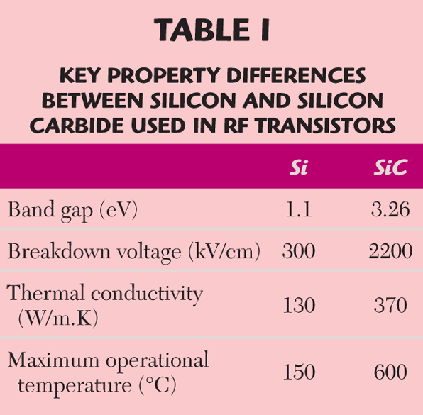
Table 1 highlights the key property differences between silicon as used in conventional silicon RF transistors and silicon carbide.
This size/weight factor is of paramount importance for military platforms that need to maximize payload. However, from a commercial perspective, at power levels of 500 W and above, the size and weight constraints associated with conventional power amplifiers force the situation where the majority of power amplifiers in test stations are immobile. With the advent of silicon carbide, portability is an option that can be capitalized on. For instance, sharing high capital cost equipment between test stations and between test sites is now a practicality.
RF250 Architecture
The amplifier RF topology follows a Corporate Structure Architecture (CSA) approach, as shown in Figure 1.
The name comes from the similarity of the layout of the RF building blocks to that of a corporate organization chart, but turned 90° clockwise. The advantages of the CSA design methodology have been proven in the company’s microwave range and are now being exploited in this RF range.
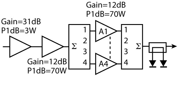
The building block of the amplifier’s output rank is a 200 to 1000 MHz, 70 W P1dB power module, with a typical gain of 12 dB. Concentrating on the development of a single common power module has the virtue that a high percentage of engineering resource (microwave, electrical, thermal, mechanical) can be focused to design a component around which a reliable system can be built.
Output Rank Power Module
The transistor at the heart of this module is the CRF-24060, a silicon carbide MESFET from Cree Inc. A combination of simulation work using the supplied large-signal model, supplemented by load pull data collected within MILMEGA, has brought about the development of high quality matching networks that require minimal tuning to be applied at the manufacturing stage. These matching circuits were optimized for P1dB performance.
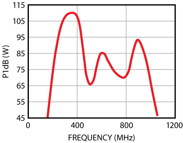
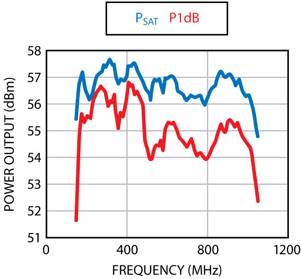
Power is developed within the module by combining two transistors in a balanced pair configuration, using one level of quadrature combining. This, in addition to the inherent robustness of the SiC devices, enables the modules to absorb 100 percent reflected power, even when the module is operating at full output power. This can be a significant benefit to the system designer, if the amplifier is required to operate into high VSWR conditions. The P1dB performance of the module over the band of interest is shown in Figure 2.
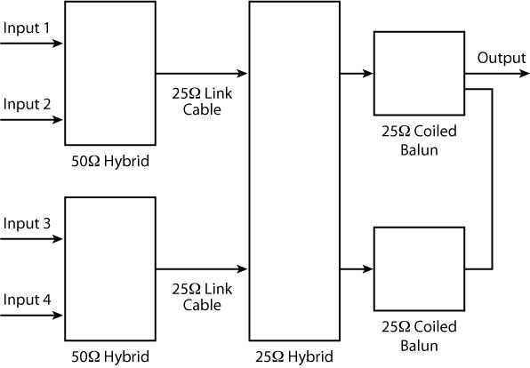
4:1 Output Combiner
In designing the final output combiner it was vital that the insertion loss from input to output is an absolute minimum, thus reducing the gain and power requirements on the system preamplifier stages. The major building block of the output combiner is a ferrite-loaded hybrid, which functions as a two-way splitter/combiner. It also provides adequate isolation between its inputs and exhibits low insertion loss. Two versions of these hybrids are used, one a 50 Ω device and the other a 25 Ω device.
Figure 3 is a representation of this architecture in which two, two-way, 50 Ω hybrids combine the power from four RF inputs, resulting in two 25 Ω outputs. Each 25 Ω output then feeds a 25 Ω hybrid providing isolation between pairs of input sources. A pair of 25 Ω coiled baluns then impedance match to 50 Ω. Figure 4 shows the measured transmission results obtained across the frequency band for this structure. Note the flatness of the amplitude response and the low insertion loss.
Control System
The overall control and sensing of the amplifier system is partitioned between three separate processors. First, the central control processor controls and monitors the system modules and provides the BIT functionality.
Second, the local control processor acts as the interface between the front panel controls/indicators and the central control processor. It also senses and displays the forward and reflected RF power levels.
Finally, the communications processor acts as the interface between the central control processor and the outside world. Additionally, it permits expanded control and sensing at the next level of system integration, which is when multiple amplifier systems are interconnected. Each processor has in-circuit programming capability, enabling the software to be updated.
To provide BIT functionality, health signs, including voltage and current consumption, are monitored for each module. Key modules such as those in the RF line-up are monitored via direct connections to the central control processor. Less critical modules are monitored every few milliseconds via a multiplexer. A fault causes one of a column of LEDs to light. For convenience, the column is visible through the amplifier front panel.
Expandable Control Capability

Initiated by detection of the presence of a specialized interconnecting cable, the expanded control feature permits any amplifier within a combination of amplifiers to be the master or slave in the overall operation of the combined amplifier system. Commands between the separate amplifiers are controlled and synchronized by the communications processors in each amplifier, the protocol being that the initiator of a command becomes the master with the other amplifiers in the system responding as slaves. The BIT functionality passes through to this next level of amplifier integration.
The Final System
The efficiency of the output combining circuit is demonstrated by the power achieved in the final system, as shown in Figure 5. The RF250 delivers a P1dB performance of 250 W minimum, peaking at 480 W with Psat a minimum of 410 W, peaking at 585 W. This represents state-of-the-art power density for this type of product resulting in an amplifier, which is approximately three times smaller and lighter than comparable units.
Conclusion
The inherent benefits of silicon carbide RF power transistor technology have been combined with the CSA design approach, together with distributed embedded intelligence to create a robust UHF power amplifier family providing high reliability, exceptional power density, ease of power upgrade and portability.
MILMEGA,
Isle of Wight, UK
+44 (0) 1983 618004,
www.milmega.co.uk.
RS No.300