
Conventional radiatively coupled, ultra-high frequency radio-frequency identification (UHF RFID) tags have certain limitations: they are physically large and do not operate well in or close to aqueous fluids. Recently, the use of tags configured to use inductive instead of, or as a supplement to, radiative coupling has been advanced as an alternative application model for UHF RFID. Inductively coupled tags require reader antennas that provide significant magnetic fields.
The mutual inductance between two loop antennas is strongly influenced by the antenna diameter. A small loop produces a strong magnetic field along its axis, but the field falls rapidly when the sensing coil is moved more than approximately one diameter above the larger loop. A large loop produces a more modest peak field, but the extent of the field is larger, scaling with its diameter. Therefore, there is an optimal size for best read range for any given peak loop current and coupling requirement.1 Two obstacles are encountered when one attempts to design simple loop antennas for UHF (approximately 900 MHz) near-field readers. Antennas of intermediate diameter (between 2 and 5 cm) are awkward to match to a 50 Ω input, due both to low radiation resistance and high input impedance: loop antennas have a parallel resonance in this size range. As the antenna diameter approaches the series resonant size (approximately λ/π) the current distribution shifts to produce a change in sign of the current flow, and the antennas produce relatively little magnetic field on axis.2,3
Segmented Loop Antennas

In order to address the problems cited above, a segmented loop antenna has been constructed. Each segment is composed of a metal line forming a polygonal face and a series capacitor to the next segment.
Each segment forms a resonant line, avoiding the accumulation of inductive reactance that otherwise impedes matching.
Because at resonance the voltage across the segment is real, phase does not accumulate around the loop, and the current around the loop remains approximately in phase and of the same sign, thus producing a substantial magnetic field along the axis.
Example antennas are shown in Figures 1 and 2.

Model and Measurement Results
To simulate the loop resonance, a 2.5D electromagnetic solver software was used and an N-port S-parameter block was extracted. For example, for the 10 cm loop, a 32-port S-parameter file was extracted. This file was used in a linear simulator to determine the proper capacitances between segments, cascade the input of the loop with the S-parameter results of a balun and add matching components. Since the radiation resistance is very small compared to the 50 Ω coaxial feed line, the loop match is very sensitive to the reactance values. To make the matching more robust and attain better manufacturability, a resistor was mounted on the opposite side of the antenna feed to decrease the Q of the loop sufficiently. Commonly, a loop antenna with a length much smaller than its exciting wavelength is referred to as a small loop. Small loops have constant current phase along the loop wire and have the capability of generating a strong near-field magnetic field. On the other hand, due to the small circumference, the magnetic field tapers off very quickly beyond a distance equivalent to one loop diameter. Increasing the coil size will increase the read-distance of near-field tags but have the disadvantage that, at UHF frequencies and for practical read distances, the loop is not small compared to the wavelength. A 10 cm diameter coil, for example, is roughly one wavelength in perimeter and will have current nulling and a phase-inversion along the circumference.

Figure 3 shows the surface current along a 10 cm coil driven at 915 MHz. The top and bottom show current nulls and the left portion is out of phase with the right.
Segmenting and combining the parasitic inductance of each section with a lumped capacitor will cause the large loop to behave electrically like a small one.
The current will remain constant along the loop and provide a strong magnetic field (see Figure 4). This physically large but electrically small loop has very little radiation resistance and thus can be driven with significant strong currents without violating government radiation limitations.
Distributing the capacitances also relaxes the voltage breakdown requirements allowing stronger drive power.

The measured return loss for the 5 cm loop is shown in Figure 5, and for the 10 cm loop in Figure 6, demonstrating the good bandwidth matching obtained with small and large loops.
Inductive Coupling Improvement
The inductive coupling was measured using an 8 mm diameter simple loop, matched to 50 Ω. The small loop was matched to a 3 kΩ terminating resistor placed opposite the loop feed using a 1.3 pF capacitor.
A loop of this diameter has a radiation resistance much less than 1 Ω, so coupling between the small and large loops ought to be almost purely inductive.
The loop incorporated a wire-wound balun to avoid common-mode coupling between the antenna under test and the shield of the coaxial hookup cable.
In each test the sense antenna was placed above and parallel to the plane of the larger loop antenna under test. A 10 cm diameter segmented loop was compared to a simple single-segment loop of the same size and shape.

The results are shown in Figure 7. The use of the segmented loop results in an approximately 20 dB increase in coupling to the small test loop.
The return loss is sensitive to the environment, despite the fact that the antennas are excited through a balun. For example, the antenna is detuned if placed directly on a static-dissipative surface.
The results reported in the next section are obtained with the antenna mounted in a polyethylene box several centimeters away from other surfaces.
It seems likely that the use of a fairly high dielectric-constant baseplate combined with appropriate adjustment of the segment parameters will produce an antenna less affected by nearby objects, but this has not yet been confirmed by experiment or analysis.

Read Range
UHF RFID tags that couple inductively can be constructed using a loop antenna rather than the conventional short dipole; a test tag was constructed by removing the dipole from a conventional Texas Instruments Class 1 Generation 2 inlay, leaving only the 10 X 13 mm tuning loop.
Using this type of tag, the read range of the segmented antennas was tested employing a conventional WJ Communications MPR6000 reader module.
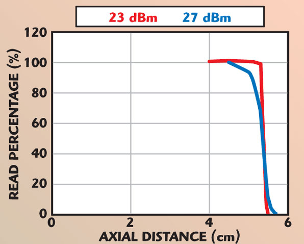
The 5 cm diameter segmented loop results in a sharply defined read range of approximately 5.5 cm on axis, as shown in Figure 8.
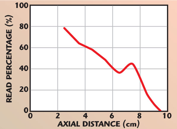
The read percentage for the 10 cm diameter segmented loop falls more gradually with distance, but reads are possible out to approximately 8.5 to 9 cm along the axis (see Figure 9).

The detailed origins of the different behavior of the small and large antennas have not yet been examined, although since the peak magnetic field on axis is higher and the fall-off more abrupt for a small antenna, some difference in behavior is to be expected.
The importance of reduced read rates is application-dependant. A single read using ISO 18000-6C-compliant tags with the inventory parameter Q = 0 or Q = 1, for instance, requires a few milliseconds.
In some applications, it is only necessary that a tag be read once and an ample amount of time may be available, whereas in other usage models, a large number of tags may be present and must be read reliably.
The authors have verified that at least in some circumstances reads are roughly Poisson-distributed, so to achieve 99 percent reliability for a single read, for example, a tag should average 6 to 8 possible reads.
Therefore, the practical range resulting from the behavior shown for the 10 cm diameter segmented loop will vary depending on the exact application.
It may also be possible to optimize the antenna performance to improve reads at the 6 to 8 cm range.
Conclusion
Inductive loop antennas can be constructed at sizes comparable to the resonant diameter by dividing the loop into individually resonant segments.
Acknowledgments
The authors would like to thank Kendall Kelsen of WJ Communications for his assistance in constructing some of the antennas, and Ron Oliver of Impinj for helpful discussions.
References
- K. Finkenzeller, RFID Handbuch, Carl Hanser Verlag, München, Germany, 3, Aufl., 2002 (English translation available from Wiley & Sons Ltd., Chichester, UK, Second Edition, 2003).
- C. Balanis, Antenna Theory, Third Edition, Chapter 5, Wiley Interscience, Hoboken, NJ, 2005.
- W. Stutzman and G. Thiele, Antenna Theory and Design, Chapter 5, John Wiley & Sons Inc., Hoboken, NJ, 1981.