
This article presents a novel microstrip structure for double controllable notched bands implementation in an ultrawideband (UWB) bandpass filter (BPF). The double notched bands are created by introducing the proposed structure with modified multi-mode resonator (MMR). The filter, with a passband from 2.95 to 10.84 GHz, has notched bands at 5.87 GHz (WLAN) and 7.61 GHz (military communication satellite) frequencies, insertion loss of less than 0.2 dB, return loss of better than 16.7 dB, group delay variation of less than 0.2 ns in the three passbands, rejection loss of 37.2 and 30 dB, fractional bandwidth of 114 percent and a wide stopband.
Ultrawideband wireless communication technology has attracted wide attention since the Federal Communications Commission (FCC) released the unlicensed use of the frequency range from 3.1 to 10.6 GHz for commercial communication applications in 2002. Recently, the development of new UWB filters has increased via different methods and structures.1-7 Due to the existing undesired narrowband radio signals, such as wireless local area network (WLAN) and military satellite communication systems that may interfere with the UWB range defined by the FCC, it is desirable to introduce single or multiple notched bands to avoid interferences from the existing wireless communication into UWB BPFs. Some techniques have been studied.8-13
In this article, a UWB BPF with controllable double notched bands is designed, fabricated and tested. This technique is based on parallel-coupled lines. The parallel-coupled lines are designed to generate double notched bands inside a wide passband. The proposed structure is to be applied to an improved microstrip-line single-stage MMR. Previously, an MMR with three stubs was described7 and in this article, the MMR was improved, using four stubs and two parallel coupled lines to relocate the first three resonant modes within the UWB band, while pushing up the next mode to make up a wider upper stopband. The modified multiple mode resonator and the double coupled feed lines can work together to create the desired UWB BPF with double notched bands. By properly adjusting the gap between the parallel coupled lines, the desired double notched bands can be obtained. The proposed filter is realized on a low cost microstrip substrate with a relative dielectric constant of 6.15 and a thickness of 31 mil.
Notched Band Characterization
Figure 1 illustrates the layout of the proposed microstrip double notched band structure. Sun and Zhu4 have proposed a structure consisting of three coupled lines with symmetric loaded stubs, to achieve a UWB BPF with a tight coupling degree and enhance the out-of-band performance of an earlier work.1 Shaman and Hong10 improved the approach of Sun and Zhu4 by developing a new technique for notch implementation in UWB BPFs. This technique is to be used on parallel coupled lines with asymmetric loading stubs.
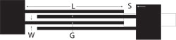
Fig. 1 Configuration of the proposed microstrip coupled lines.
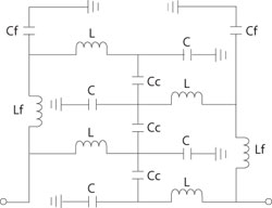
Fig. 2 LC equivalent circuit of the proposed resonator.
Here, the purpose is to generate the double narrow notched bands, using the structure depicted, with L = 5.7 mm, G = 0.1 mm, S = 0.2 mm and W = 0.1 mm. The length of the lines is chosen to be a quarter-wavelength long, at approximately 7 GHz, to obtain a wide passband. To have a better understanding of the proposed resonator, its LC equivalent circuit is derived as shown in Figure 2. In this circuit, Cf and Lf represent the capacitance and inductance of the feeding lines, respectively, while C and L are used to model the same parameters for the interdigital fingers and finally Cc represents the coupling between these fingers.
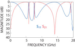
Fig. 3 EM-simulated response of the resonator.
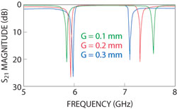
Fig. 4 Simulated response as a function of G.
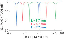
Fig. 5 Simulated response as a function of L.
Figure 3 displays the EM-simulated insertion and return loss of the proposed structure on a substrate with a dielectric constant of 6.15 and a thickness of 31 mil. To evaluate the resonator structure, the effects of dimension variations on the resonator response are studied. The two dimensions that have the most significant influence and can be used to control the position of the notched bands are G and L. The EM-simulated results of the proposed resonator as a function of G and L variations are shown in Figures 4 and 5, respectively. As seen in the figures, by increasing the value of G, both notched frequencies change, so that the f1 frequency increases and the f2 frequency decreases. By increasing the value of L, both of the notched bands move to lower frequencies.
UWB BPF with Double Notch
Figure 6 illustrates the layout of the modified MMR. Li and Zhu’s MMR7 has three stubs and here, it has been improved by using four open stubs with two parallel coupled lines. In this way, with adjusting the length of the stubs L1 and L2, the first three resonant modes have been relocated within the UWB passband, while pushing up the next mode to obtain a wider upper stopband. In addition, in this structure, the modified MMR has two parallel coupled lines. As shown in Figure 7, as L2 is lengthened, the first and the second resonant frequencies keep almost unchanged, while the third frequency is moved down and the two other open stubs, with lengths L1, can change the location of the resonant frequencies, so that as L1 lengthened, the first resonant frequency is kept almost unchanged, while the second and the third frequencies are moved down, as shown in Figure 8.
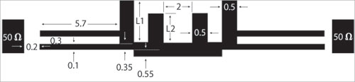
Fig. 6 Layout of the modified stub-loaded MMR, which are weakly capacitive-coupled.
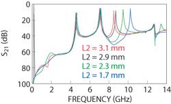
Fig. 7 S21 magnitude of the stub-loaded MMR structure vs. L2.
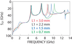
Fig. 8 S21 magnitude of the stub-loaded structure vs. L1.
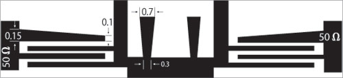
Fig. 9 Microstrip layout of the final UWB BPF with double notch changing the shape of the second stubs.
By attaching the modified MMR to the proposed microstrip coupled lines, a UWB BPF with double notched bands can be obtained, and by changing the gaps between the parallel coupled lines, the desired notched frequencies can be achieved. Also, with changing the shape of the second stubs as shown in Figure 9, the stopband can be improved as shown in Figure 10. By changing the upper coupled line to a trapezoid shape, the notched frequencies moved up slightly (approximately 0.1 GHz). So the final modified structure for an UWB BPF with two notched frequencies at f1 = 5.87 GHz (WLAN) and f2 = 7.61 GHz (military communication satellites) is obtained. Figure 11 is a photograph of the fabricated compact filter.
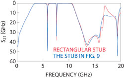
Fig. 10 EM-simulated insertion loss of the UWB BPF with double notch changing the shape of the second stub.
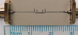
Fig. 11 Photograph of the fabricated compact filter.
Simulated and Measured Results
The filter is designed and fabricated on a substrate with a relative dielectric constant of 6.15 and a thickness of 31 mil. Its filtering performance is simulated using the Agilent Momentum software. A 5 mm long microstrip feed line is added to both input and output. It occupies a small size of 17.04 × 3.25 mm.
The final filter is capable of reducing the insertion loss in the three passbands to less than 0.2 dB, the return loss over the three passbands is greater than 16.7 dB, the group delay variation in the three passbands is less than 0.2 ns, the rejection loss is more than 37.2 dB at the midband frequency of the first notched band and better than 30 dB at the midband frequency of the second notched band. The fractional bandwith is 114 percent. Also, a wider stopband less than −12.2 dB up to 19.5 GHz has been obtained. Figures 12 and 13 show the simulated and measured frequency response of the S-parameters magnitude and the group delay, where an excellent agreement is obtained.
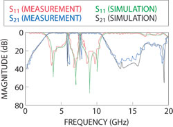
Fig. 12 EM-simulated and measured S21 and S11 magnitudes of the final UWB BPF with double notch.
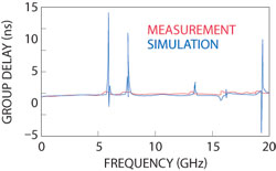
Fig. 13 EM-simulated and measured group delay of the final UWB BPF with double notch.
Conclusion
This article has presented a coupling structure for implementing double notched bands in UWB BPFs. It is based on four parallel-coupled lines, which can provide a tight coupling within the FCC-regulated UWB passband, and introduces two notches inside the passband at the desired frequencies. It has been applied to a single stage modified MMR to produce two narrow notched bands inside its passband. The notched frequencies are controllable. The stopband of the final structure has been improved.
The UWB BPF with double notched bands at (5.87 GHz) WLAN frequency and (7.61 GHz) military communication satellite frequency, with small in-band insertion loss, large in-band return loss, high rejection loss and small group delay variation has been obtained. Excellent agreement between the simulated and measured results is obtained.
References
1. L. Zhu, S. Sun and W. Menzel, “Ultra-wideband (UWB) Bandpass Filters Using Multiple-mode Resonator,” IEEE Microwave and Wireless Components Letters, Vol. 15, No. 11, November 2005, pp. 796-798.
2. H. Wang, L. Zhu and W. Menzel, “Ultra-wideband Bandpass Filter with Hybrid Microstrip/CPW Structure,” IEEE Microwave and Wireless Components Letters, Vol. 15, No. 12, December 2005, pp. 844-846.
3. J. Gao, L. Zhu, W. Menzel and F. Bogelsack, “Short-circuited CPW Multiple-mode Resonator for Ultra-wideband (UWB) Bandpass Filter,” IEEE Microwave and Wireless Components Letters, Vol. 16, No. 3, March 2006, pp. 104-106.
4. S. Sun and L. Zhu, “Capacitive-ended Interdigital Coupled Lines for UWB Bandpass Filters with Improved Out-of-band Performance,” IEEE Microwave and Wireless Components Letters, Vol. 16, No. 8, August 2006, pp. 440-442.
5. T.N. Kuo, S.C. Lin and C.H. Chen, “Compact Ultra-wideband Bandpass Filters Using Composite Microstrip-coplanar-waveguide Structure,” IEEE Transactions on Microwave Theory and Techniques, Vol. 54, No. 10, October 2006, pp. 3772-3777.
6. K. Song and Y. Fan, “Compact Ultra-wideband Bandpass Filter Using Double-line Coupling Structure,” IEEE Microwave and Wireless Components Letters, Vol. 19, No. 1, January 2009, pp. 30-32.
7. R. Li and L. Zhu, “Compact UWB Bandpass Filter Using Stub-loaded Multiple-mode Resonator,” IEEE Microwave and Wireless Components Letters, Vol. 17, No. 1, January 2007, pp. 40-42.
8. K. Li, D. Kurita and T. Matsui, “UWB Bandpass Filters with Multi Notched Bands,” Proceedings of the 2006 IEEE 36th European Microwave Conference, pp. 591-594.
9. H. Shaman and J.S. Hong, “Ultra-wideband (UWB) Bandpass Filter with Embedded Band Notch Structures,” IEEE Microwave and Wireless Components Letters, Vol. 17, No. 3, March 2007, pp. 193-195.
10. H. Shaman and J.S. Hong, “Compact Asymmetric Parallel-coupled Lines for Notch Implementation in UWB Filters,” IEEE Microwave and Wireless Components Letters, Vol. 17, No. 7, July 2007, pp. 516-518.
11. S.W. Wong and L. Zhu, “Implementation of Compact UWB Bandpass Filter with a Notch-band,” IEEE Microwave and Wireless Components Letters, Vol. 18, No. 1, January 2008, pp. 10-12.
12. W. Menzel and P. Feil, “Ultra-wideband (UWB) Filter with WLAN Notch,” Proceedings of the 2006 IEEE 36th European Microwave Conference, pp. 595-598.
13. G.M. Yang, R. Jin, C. Vittoria, V.G. Harris and N.X. Sun, “Small Ultra-wideband (UWB) Bandpass Filter with Notched Band,” IEEE Microwave and Wireless Components Letters, Vol. 18, No. 3, March 2008, pp. 176-178.