
High performance bandpass filters, with miniaturized size, narrow bandwidth, wide stop band and low cost, are required in modern wireless communication systems, especially in mobile and portable Internet systems. Planar reduced-size filters, such as λ/2 hairpin resonator1 and slow-wave resonator2 filters have already been published.
These filters have the advantage of good harmonic suppression, but are still too large to be inserted into commercial transceiver systems. The quarter-wavelength ceramic combline filter, using a high dielectric constant material,3 is another type of miniaturized bandpass filter. Nevertheless, the electrical length of the transmission line itself is not reduced in this combline filter.
In this article, an extremely miniaturized filter is introduced, resulting from Hirota’s reduced λ/4 transmission line.4 It shows a wide upper stop band, because the lumped capacitors used in this filter suppress the upper spurious signals. In addition, the electrical length of the proposed bandpass filter can be controlled arbitrarily in theory and reduced to just a few degrees. A filter has been designed and fabricated at 300 MHz to emphasize the effect of the size reduction method, since the lower the resonant frequency, the longer the electrical length.
Size Reduction Method for a λ/4 Transmission Line
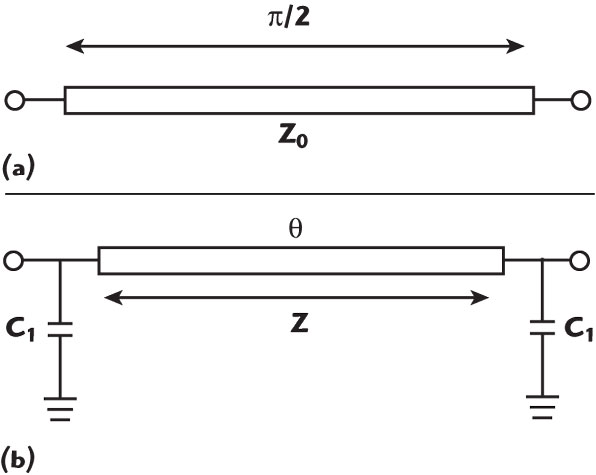
A λ/4 transmission line can be shortened by using a combination of a short tranmission line and shunt lumped capacitors,4 as shown in Figure 1. The shorted line parameters are
Z = Z0/sinθ (1)
ωC1 = (1/Z0) cosθ (2)
The characteristic impedance Z of the shortened line increases as the electrical length θ of the shortened line gets smaller. If θ is very small, Z will become too high to be realized.
Up to now, the limitation of the electrical length of the tramission line is approximately π/8 to π/12. Therefore, it is necessary to overcome the high impedance of the shortened transmission line.
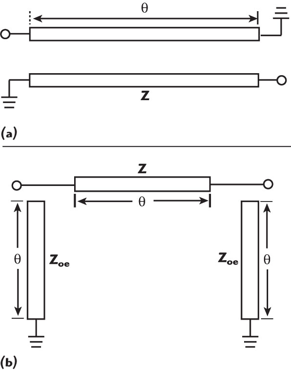
Figure 2 shows the diagonally shorted coupled lines and their eqivalent circuit.5 The characteristic impedance of the diagonally shorted coupled lines is given by
Z = (2 Z0eZ0o)/(Z0e–Z0o) (3)
From Equation 3, it can be seen that the shorted coupled lines are proper for extremely miniaturized λ/4 transmission lines as the high characteristic impedance can be easily attained by choosing Z0e close to Z0o.
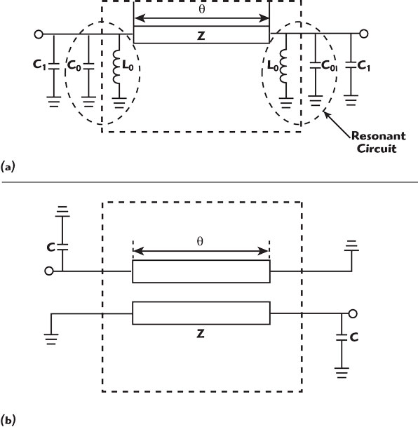
As shown in Figure 3, the artificial resonant circuits are inserted in Hirota’s lumped distributed λ/4 transmission line, and the high impedance transmission lines with shunt lumped inductors can be replaced by coupled lines.
The parts in the two dotted square boxes are equivalent when the following equations are satisfied6
ω L0 = Z0e tan θ (4)
ω L0 = 1/(ω C0) (5)
C = C0 + C1 (6)
Thus, it is feasible to obtain a very high impedance using coupled lines. The peculiar feature of this extremely miniaturized λ/4 transmission line is that the resonant circuits are located at the edge side of the tranmission line.
When the miniaturized λ/4 tranmission lines are connected in series, the cascaded circuit becomes a typical bandpass filter, as shown in Figure 4, because the λ/4 section can be used as an admittance inverter.
The bandwidth of the filter can be controlled by the coupling coefficient since the bandwidth of a diagonally end-shorted coupled line is closed related to the coupling coefficient.7
Simulation and Experimental Results

A two-stage miniaturized bandpass filter, with f0 = 300 MHz and Z0 = 50 Ω, was designed with the electrical length of the coupled lines equal to 5.2°.
The designed circuit was simulated using HFSS and the results are shown in Figure 5.
When the two miniaturized λ/4 transmission lines are connected directly (L = 0 mm), a distorted shape appears. That is because there is an unwanted coupling, which cannot be neglected.
It is caused by the 180° phase difference between the edge sides of the cascaded two stages and their distance is too close.
Therefore, it is necessary for a very small transmission line of length θ to be inserted between the resonators to block the unwanted coupling, as shown in Figure 6.
When the bandpass filter is simulated by HFSS with a small transmission line (L = 3 and L = 5 mm) inserted, it operates normally. To the authors’ knowledge, the use of this small transmission line between resonators has not been reported in the literature before.
As the size of the filter becomes smaller, this small transmission line section is needed. As shown above, the inter-stage transmission line is indispensable and the filtering characteristics get better as the line length is longer.
Considering the size of the circuit, 5 mm is chosen as the length of the inter-stage line. The miniaturized bandpass filter was fabricated on a 1.57 mm thick Teflon substrate with a relative permittivity of 10 and a conductor thickness of 35 μm.
The total physical length of the fabricated filter is approximately 1.7 cm. A photograph of the filter is shown in Figure 7.
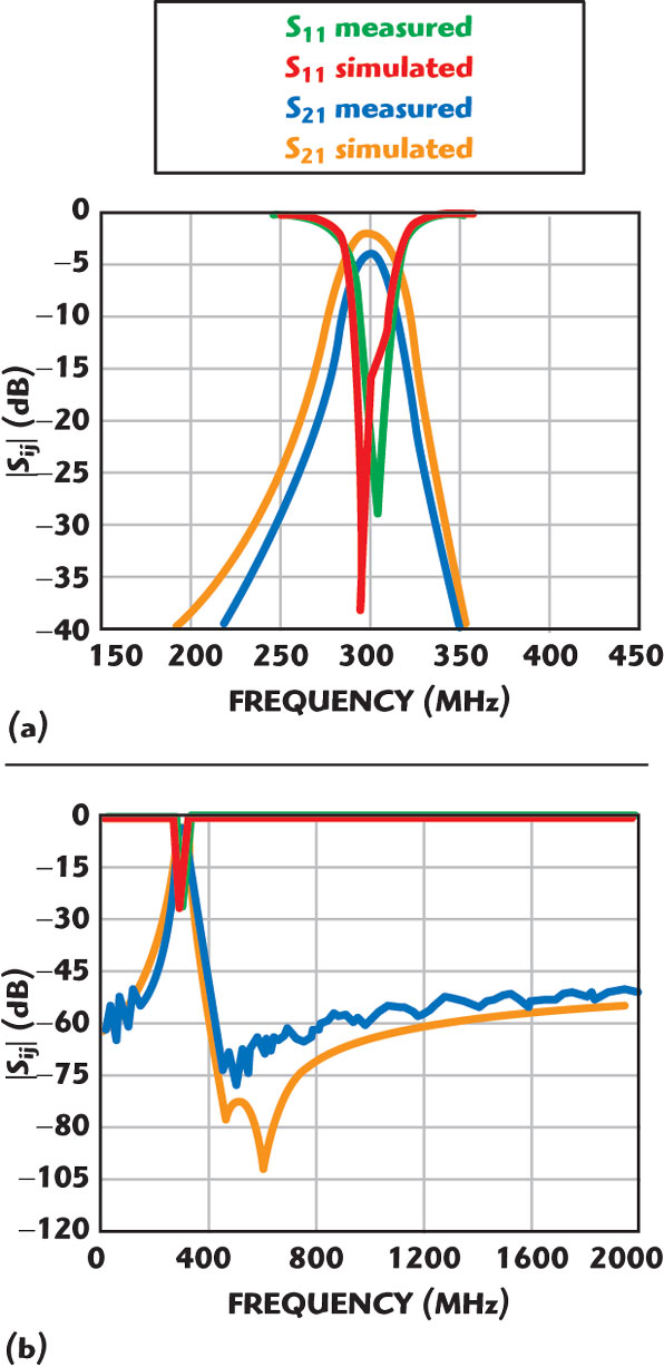
The HFSS simulation and the experimental results have been compared. MIM capacitors are used in the simulation of the filter circuit because the equivalent circuit information for lumped capacitors is not known. The frequency responses of the passband filter over narrow and wide ranges are shown in Figure 8.
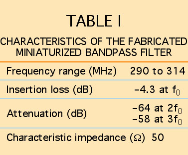
The center frequency of the actual circuit is 304 MHz and the insertion loss is 4.3 dB. The filter has an extremely wide upper stop band (S21 < –45 dB), up to 7f0, because the lumped shunt capacitors suppress harmonics.
Although the λ/2 hairpin resonators and slow-wave open-loop resonators can also suppress harmonics, they just expand the stop band by shifting the spurious frequencies resulting from the slow-wave effect.

The experimental results of the proposed filter show that the harmonics have disappeared, resulting in an ultra-wide band. The measured results of the experimental filter are summarized in Table 1.
Conclusion
An extremely miniaturized bandpass filter, using a combination of diagonally shorted coupled lines and lumped capacitors, is proposed in this article.
By using this method, the size of the bandpass filter can be reduced by more than 95 percent, compared with the size of a conventional one and a wider upper stop band is achieved.
The measured results agree well with the theoretical ones. This new type of filter can be extended to MMIC technology.
References
- M. Sagawa, K. Takahashi and M. Kakimoto, “Miniaturized Hairpin Resonator Filters and Their Application to Receiver Front-end MICs,” IEEE Transactions on Microwave Theory and Techniques, Vol. 37, No. 12, December 1989, pp. 1991–1997.
- J. Hong and M.J. Lancaster, “Theory and Experiment of Novel Microstrip Slow-wave Open-loop Resonator Filters,” IEEE Transactions on Microwave Theory and Techniques, Vol. 45, No. 12, Part II, December 1997, pp. 2358–2365.
- H. Yao, C. Wang and K. Zaki, “Quarter-wavelength Ceramic Combline Filter,” IEEE Transactions on Microwave Theory and Techniques, Vol. 44, No. 12, Part II, December 1996, pp. 2673–2679.
- T. Hirota, A. Minakawa and M. Muraguchi, “Reduced-size Branch-line and Rat-race Hybrids for Uniplanar MMICs,” IEEE Transactions on Microwave Theory and Techniques, Vol. 38, No. 3, March 1990, pp. 270–275.
- G. Matthaei, L. Young and E.M.T. Jones, Microwave Filters, Impedance-matching Networks and Coupling Structures, Artech House Inc., Norwood, MA, p. 220.
- I. Kang and J. Choi, “A New Reduced-size Lumped Distributed Power Divider Using the Shorted Coupled Line Pair,” Korea Electromagnetic Engineering Conference, Vol. 13, No. 1, November 2003, pp. 283–287.
- I. Kang and K. Wang, “A Broadband Rat-race Ring Coupler with Tight Coupled Lines,” IEICE Communications, Vol. e88-B, No. 10, 2005, pp. 4087–4089.
 In-ho Kang received his PhD degree from Sogang University, Seoul, South Korea, in 1995. He is currently an associate professor in the division of radio and information communication engineering at Korea Maritime University (KMU), Pusan, South Korea. He is a founder of SOON Micro-technology, which was spun off of KMU in 2005. His research interests include MMIC filters for the RF single chip for 5.5 GHz WLAN, WiMAX and UWB applications, and MMIC filters for power amplifier harmonic suppression.
 Haiyan Xu received her BS degree in electronic and information science and technology from Qingdao University, Qingdao, China, in 2004. She is currently working toward her MS degree in radio and information communication engineering at Korea Maritime University, Pusan, South Korea. Her research interests include RF/microwave circuit and system design.