
Most radar warning (RW), electronic countermeasures (ECM) and electronic intelligence (ELINT) systems employ instantaneous frequency measurement (IFM) to identify threats, map the electronic battlefield and eventually implement deceptive countermeasures.

In its development of systems in this sector Elisra has made advances with the introduction of its Digital Instantaneous Frequency Measurement (DIFM) receiver, which is shown in Figure 1 as a block diagram. This receiver offers the user large broadband instantaneous frequency coverage of 2 to 18 GHz, high dynamic range, high frequency measurement accuracy and fast throughput time—less than 400 ns.
RF and IF/Video
To provide an understanding of how these performance figures are achieved one must examine more closely the operation of the new DIFM receiver, starting with the RF and IF/video sections. First, an RF pulse (100 ns minimum) is applied to a limiting RF amplifier where the limited RF power is channelized into M channels and then downconverted to an IF baseband by internal local oscillators.

The M IF basebands are processed in the IF/video card to generate the internal signal and to define the band code.
The IF baseband channels are then combined into two IF outputs to drive the digital IFM card, which is based on digital processing single bit IF samples and is shown in Figure 2. A functional block diagram of the digital IFM is shown in Figure 3.
The input IF signal is sampled at a high rate to provide the necessary IF bandwidth according to the Nyquist criteria. Sampling is performed with single bit resolution so that the incoming signal is, in fact, limited. As a result the sine wave is transformed into a square wave.
DIFM: Principle of Operation

Digital processing is analogous to that of an analog IFM, while enjoying the benefits of digital processors. The basic principle is that the incoming bit stream is subject to a predetermined delay after which it is auto-correlated. The analog mixing and low pass filtering is replaced in the digital domain by auto-correlation (binary XOR) and summation of the resultant bits.
For an incoming bit stream bk, consisting of N bits, the auto-correlation for a delay of d bits is defined as
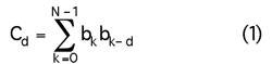
It may be helpful to try to visualize the auto-correlation sum as the area enclosed by two overlapping square waves, representing the incoming square wave and its delayed replica (where the two waves are different, the XOR will contribute a ‘1’ bit to the sum).
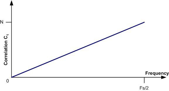
Thus, for a delay of 1 bit, each cycle will contribute two ‘1’s to the overall sum. Due to the fact that within a sequence of N bits there are N/T (or Nf) cycles, it is easy to see that C1 = 2Nf, where f is the normalized frequency of the signal with respect to the sample rate fs. This relationship, depicted in Figure 4, enables a direct calculation of the signal frequency from the value of C1.
However, this result has only N discrete values and may not provide the desired accuracy and resolution. Increasing the delay d and calculating Cd improves the situation. Following this same reasoning, each cycle now contributes 2d to the value of Cd. The slope is now d times larger, leading to a stronger frequency response—a small change in frequency generates a large change (d times) in the auto-correlation value.
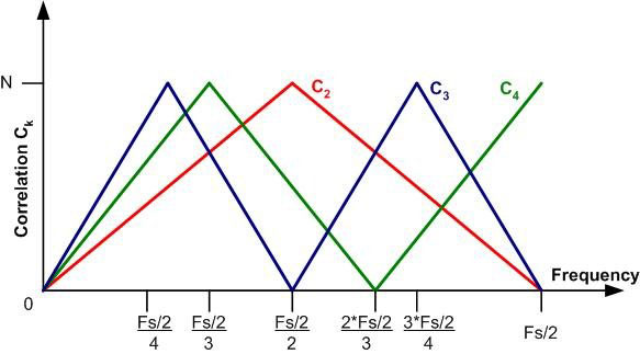
If C1 reaches the maximum value N at the maximum allowable frequency fs/2, Cd will reach its peak value at fs/(2d). At this point it will begin to decrease and the result will be a triangular wave with d slants spanning the 0…fs/2 frequency range. Figure 5 demonstrates the relationship between Ck and the frequency. Thus, while Cd is d times more accurate than C1, it also produces d ambiguous results.
The frequency measurement procedure of the DIFM receiver consists of several successive stages. Each provides a frequency measurement with improved accuracy over the previous stage and is accurate enough to solve the ambiguity of the subsequent stage. The successive stages do not utilize successive delay values, as the accuracy provided by a given step is generally good enough to advance to a delay value somewhat larger than that of the current stage.
As has already been stated, this approach and mathematical foundation is also at the heart of common analog IFM circuits and digital frequency discriminator (DFD) devices.

However, the digital implementation by field programmable gate array (FPGA) devices facilitates the calculation of many different auto-correlation values, with the advantage of being unrestricted by analog HW considerations relying on physical delay lines. Similarly, the digital delay has absolute accuracy (only limited by sampling clock stability), whereas its analog counterpart suffers from instability due to environmental conditions and requires frequent calibration and maintenance.
IFM devices can suffer from reduced accuracy near frequencies that are related to the delay value. To counter this, within a given stage multiple delays of similar values are employed so that the best of them may be selected. In the analog case this provides an additional burden limiting device performance. The digital IFM, however, accommodates several stages, each supporting several different delay values. Thus, complete accuracy is ensured across the frequency range.
Another key factor is that due to the successive nature of the algorithm, the number of stages implemented may be tailored to various customer needs regarding the trade off between latency and accuracy. With systems supporting the necessary interface, the calculation procedure may be adapted on-line to suit specific system needs.
Utilization of high speed embedded multipliers in state-of-the-art FPGA devices allows simple implementation of the various stages of frequency calculation and ambiguity resolution. These also account for the short latency within which the desired frequency measurement is provided.
Through the integration of advanced RF design and sophisticated digital methods, the 2 to 18 GHz DIFM receiver is well equipped to deliver high levels of performance and operation. Table 1 illustrates the results when the device was put through its paces using automatic test equipment (ATE). Figure 6 shows the measurements of its RMS frequency accuracy over the 2 to 18 GHz band.
Conclusion
The 2 to 18 GHz DIFM receiver offers those requiring radar warning, electronic countermeasures and electronic intelligence systems a digital receiver that incorporates state-of-the-art technology to deliver large broadband frequency coverage, high dynamic range, high frequency measurement accuracy and fast throughput, therefore meeting the demands of modern military/security/countermeasures systems.
Elisra Electronic Systems Ltd., Microwave Division,
Bene Beraq, Israel
+972 3 6 6175655,
RS No. 302