
A ceramic-loaded resonator is a transmission line with one end shorted and the other “open” end connected to a capacitor to ground, as shown in Figure 1.
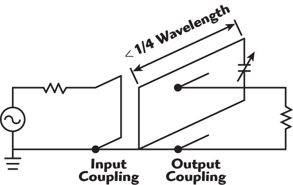
This shortens the length of the line needed to resonate at a particular frequency. The ceramic-loading capacitor overcomes the drawbacks of conventional all-metal cavity resonators, such as large housings, narrow tuning ranges and frequency drift due to RF induced heating.
Low losses are obtained by substituting some length of the transmission line with a high Q ceramic capacitor and, because the capacitor has a higher Q than the length of the transmission line section it replaces, the line is shortened and the overall Q can be increased.
The cavity resonator consists of an inner conductive post, an end cap positioned on the end of the conductive post, a ceramic disc and a top plate.

The ceramic disc is positioned between the end cap and top plate. The inner conductive post, end cap and ceramic disc are all contained within an outer cylindrical cavity extending from the bottom shorting plate to the top plate, as shown in Figure 2.
The frequency of the cavity is adjusted by increasing or decreasing the distance between the surface of the end cap and the surface of the top plate.
This is not a varactor-tuned cavity, since the ceramic dielectric constant is not voltage dependant as that of some other ceramic materials such as barium strontium titanate (BST), which typically have low Q and low power handling.
The surfaces of the ceramic disc and the conducting plates are held parallel at a certain distance. Bringing the surfaces closer together increases the capacitance, which lowers the center or resonance frequency.
Therefore, the resonance frequency of the cavity can be varied according to the amount of distance between the surfaces of the conducting plates, that is the end cap and the top plate.
The end cap and the top plate are highly conductive, in order to achieve a very high capacitor Q, which improves the resonator’s performance at high power (large current) applications, as well as in high selectivity filter applications. In addition, allowing the ceramic disc to expand and contract with temperature against the expansion and contraction of the holding mechanism results in a corresponding change in distance with temperature that results in maintaining greater frequency stability.
The loss of a coaxial transmission line is a function of its length (the longer the length the higher the loss). The loss also increases as the square root of frequency, as a result of the skin effect at RF frequencies. This holds true for coaxial cable, waveguide or a single wire.
This loss is dissipated as heat by the current carrying conductors. Loading a coaxial transmission line with a capacitance to form a resonator reduces the loss from the line, but the overall loss of the resonator will increase, unless the loading capacitor Q is of the same order as the Q of the line. However, the harmonic response of the line is extended according to the amount of shortening of the line, independent of Q.
High Q loading has been difficult to realize in the past, as a typical air capacitor Q is much lower than the coaxial line Q, due to the very small air gap required to realize the capacitance (the air gap usually being much less than the distance between the inner conductive post and outer cylinder).
Additionally, at high power, the small air gap may cause flashover sparking resulting in a breakdown. Accordingly, thin, small diameter ceramic cylinders, which reduce the length of a coaxial post, have been used to increase the flashover voltage handling and to produce extended stop band performance filters at the expense of Q. Additionally, the currents flowing on the plates of the capacitor cause loss, which in turn results in RF induced heating of the plates.
In the past, metallization schemes, such as deposited thin films or silver fired conductors, have been applied directly to the plates of the capacitor, substantially increasing these losses.
By utilizing highly conductive silver-plated copper material abutting or near the ceramic, those losses are dramatically reduced and the power handling greatly increased.
Detailed Analysis of the Transmission Line Q
The quality factor Q of a resonant electromagnetic system is defined as the product, at resonance, of the angular frequency ω and the ratio of the total energy stored in the system to the power dissipated or otherwise coupled out of the system
Q = ω • energy stored/
average power loss
which can be written as3
Q = 1⁄2 (sum of reactances
+ ω • sum of |dX/dω|)/
sum of resistances (1)
where
Q = quality factor
X = reactance
ω = 2πf
f = frequency
The impedance of the low loss transmission line shorted at one end is
Z = Zo tanh (al + jBl) = R + jX (2)
where
R = Zo sinh (2al)/(cosh (2al) + cos (2Bl))
R ≈ Zo sinh (2al)/(1 + cos (2Bl))
X = Zo sin (2Bl)/(cosh (2al) + cos (2Bl))
X ≈ Zo tan (Bl)
where
a = line attenuation (Nepers/m), (dB/m/8.686)
B = ω/c
l = line length (l < λ/4)
c = velocity of light
R = series equivalent resistance
Zo = impedance of the line
For the capacitor, X = 1/(ωC), where C is the capacitance and the Q of a single series capacitor is X/R.

Note that the Q of the line can only be approximated as X/R when 1 << λ/4, due to the reactance slope of the distributed line resonator not being the same as an inductor, as illustrated in Figure 3. At resonance, the reactance of the capacitance and the reactance of the line must be equal.
Z0 tan (Bl) = 1/(ωC)
Solving for C determines the capacitance required to resonate the shortened transmission line at the frequency f.
C = 1/(2πfZ0 (tan (Bl))
From Equation 1, the Q of a shortened length of transmission line is
Q = 1⁄2(tan (Bl) + Bl/cos2 (Bl))/(sinh (2al)/(1 + cos (2Bl))) (3)
As l approaches λ/4 in Equation 3, it reduces to the simpler form: Q = 2.1715 π/(Aλ/4)
where
A = line loss (dB/in)
λ = in inches
This is the same as 8.686 π/(Aλ)4 or π/(aλ) (4)
This is the well-known result for the Q at resonance of a λ/4 line.1
From Equation 3 and extrapolating the transmission line length toward a zero limit, the Q of the shorted transmission line approaches twice that of the λ/4 line. It is also easy to calculate the line Q when the length l is very short or near zero from the lumped circuit equivalence, approximating the line as an inductor. That Q is X/R. R reduces to Z0 al (from Equation 2). Setting X = ωL = Z0 tan (Bl), then ωL = Z0Bl. Thus, Q = Z0Bl/Z0 al, or Q = B/a = 2π /(aλ), which compared to Equation 4, is twice the Q of the λ/4 line.
Using a shortened length of line in series with a capacitor with a Q value equal to the shortened line, the resonant circuit Q is equal to the shortened line itself. Thus, the Q of the shortened transmission line and capacitor circuit is more than that of the λ/4 line, as shown in Table 1, which summarizes the case of a transmission line loaded with a resonating capacitor with the capacitor Q fixed and equal to the λ/4 line Q (4276, in this example).
Note the increase in the Q of the transmission line by shortening its length. Table 2 shows the Q of the cavity with a constant series resistance capacitor tuning the line to resonance, since a constant Q capacitor as used in the previous table would require its effective series resistance to change with reactance.
When the line length is near λ/4, nearly all the energy is in the line and a very small capacitor is required to resonate, so that the effect of its very high Q on the overall cavity Q is minimal. With a constant series resistance, the Q of the capacitor decreases since its capacitance is increasing with increased loading. High capacitive loading causes the electric field energy to be stored mostly in the dielectric disc, which acts as a shield to prevent breakdown from the end cap to the top plate.

The ceramic-loaded cavity thus allows using a shorter length post along with a high Q capacitor to realize a high power-handling filter.
Q Analysis of Loading Capacitor
Figure 4 is a photograph of a typical ceramic disk. A key point is that there is no thin film plating or silver firing on the ceramic disc itself, as these materials have low conductivities and would cause high losses, in addition to making the tuning method either fixed or mechanically abrasive, as might be done in rotating the exposed plate areas against unexposed areas of bare ceramic.
Within the ceramic disc, the electric field is vertical and the magnetic field is circular, axially symmetric and parallel to the conductive surfaces of the plates.
Currents flow on the surface of the end cap and top plate along the path from the inner to the outer diameter, perpendicular to the magnetic field. These fields are analogous to a cylindrical cavity (except there are no side walls), which, in general, has a Q proportional to the volume-to-surface area ratio.
Although some fringing capacitance exists from the outside surface of the end cap to the top plate without going through the ceramic disc, it is small relative to the ceramic capacitance.
Its net effect is combined with the ceramic capacitance when choosing the temperature coefficient of dielectric constant for the ceramic disc.
The dielectric increases the current densities on the surface of the plates where the ceramic disc is the dielectric between the conductor plates. This increased current density causes higher loss because of the presence of the dielectric. As such, the Q of the loading capacitance has to be considered not just by the dielectric Q, but also by the conductivity of the plates in contact with or near it.
Even if there was no ceramic disc, or if the dielectric losses were zero, the Q would be affected, because the net capacitor Q equals the product of the dielectric Q and the conductor Q divided by their sum, and conductor losses from this higher current density on the capacitor plates will still act to lessen the overall Q of the capacitor.
For a simple waveguide cavity filled with a zero loss dielectric, the Q of the cavity is reduced just by the presence of a dielectric in this same manner.2 There is also a trade-off in selecting the dielectric constant of the material for the loading capacitor; a high dielectric constant gives increased capacitance at the expense of increased current density and thus loss on the plates.
A low dielectric constant does not achieve the benefit of reducing the post length. Since it is desirable to reduce the length of the coaxial inner post as short as possible, a common response would be to reduce the thickness of the ceramic disc to increase the capacitance because it allows for the length of the post to be shortened.

However, there are two detrimental effects in doing so, the first being a reduction in the Q of the capacitor (reduced volume) and the second being a reduction in the flashover voltage handling.
To have high power handling and high enough Q, a thick ceramic is used, namely at least 3 mm, which allows the device to handle at least 100 W.
Comparison of the Cavity Performance
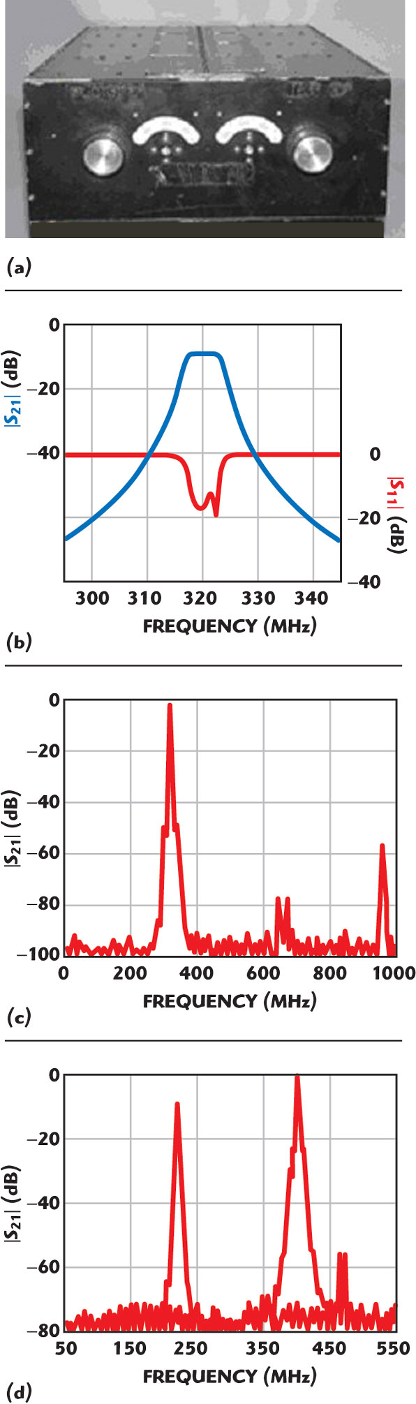
Figure 5 shows a photograph of a mechanically tuned loaded cavity filter and the actual test data showing its passband performance.
The stop band extends to over 1000 MHz, and the filter has a 100 to 400 MHz tuning range.
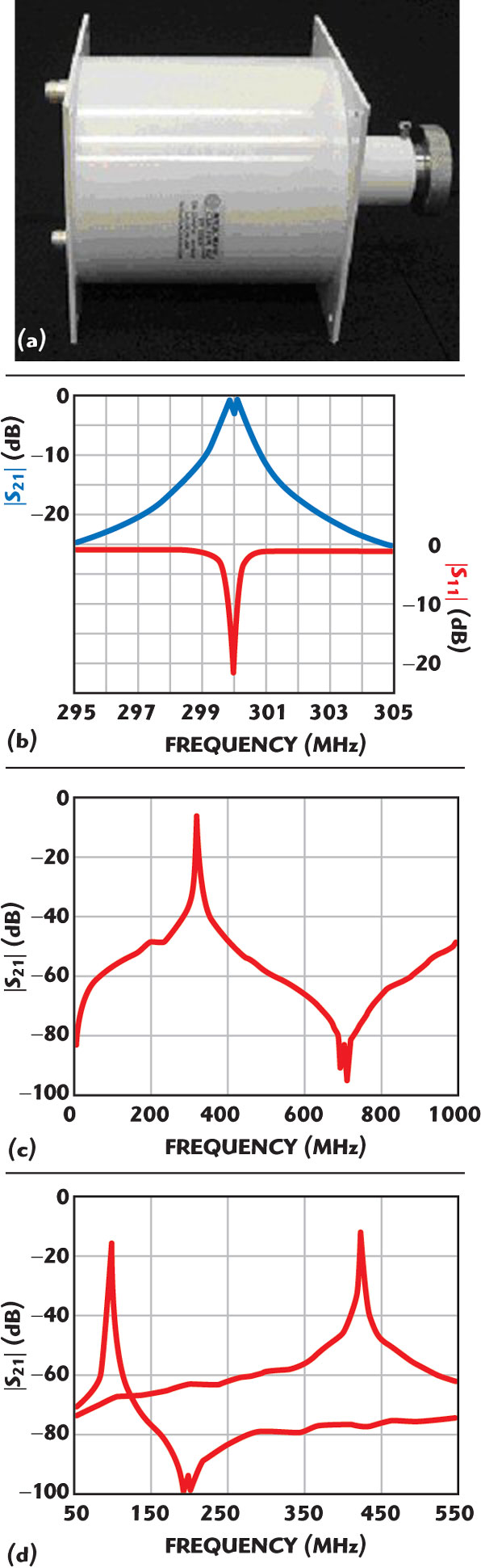
Figure 6 shows a photograph of a mechanically tuned unloaded cavity filter-similar to ones available from several filter manufacturers and the actual test data of its passband, extended stop band and tuning range, which is less than 100 MHz.
Figure 7 shows a photograph and the test data of a mechanically tuned diplexer filter, typical of the non-cavity types. Although tunable over an octave, the bandwidths are wide and generally of the order of 1 to 5 percent of the center frequency.
This four-section filter does not even provide 20 dB rejection at 5 MHz from the center frequency, compared to the response of the cavity filters, where for similar insertion loss and only a single cavity, nearly 25 dB rejection is achieved.
Conclusion
A ceramic-loaded cavity filter does not produce a second passband for a bandwidth many times the center frequency of the filter. This is of great benefit in avoiding responses to out-of-band interference signals or preventing those out-of-band signals from passing through the filter.
The ceramic-loaded cavity filter length is half that of conventional quarter-wavelength cavities. Wide frequency range tunable cavities are available from 30 to 1000 MHz in multi-octave bands, allowing modern communications equipment to be built with fewer numbers of different filters.
The insertion loss of a capacitive-loaded cavity is comparable to that of high Q conventional cavities. Its bandwidth is an order of magnitude narrower than that of a lower Q octave band tunable filter. This is very beneficial for use in direct conversion receivers.
The filter and LO synthesizer are tuned to produce a single constant IF directly from the RF avoiding multiple down conversions.
This is not even possible in the wider tuned filters, as the bandwidth of those filters is wide enough to allow passage of multiple channels, in which the LO synthesizer is tuned to select a specific channel to down-convert. The interfering image of the desired channel would also be present at the IF. By tuning the narrow band cavity filter and an LO synthesizer to only one RF channel, the undesired image is rejected, eliminating at least one down-conversion stage within the receiver.
A ceramic-loaded cavity filter has an excellent temperature stability and high power handling. By suitable selection of cables and coupling probes, notch filters, duplexers, diplexers, combiners, multiple bandpass and bandpass with notch filters are available with this new device.
References
- R.I. Sarbacher and W.A. Edson, Hyper and Ultra-high Frequency Engineering, John Wiley & Sons Inc., New York, NY, 1943,pp. 347–349.
- P.A. Rizzi, Microwave Engineering Passive Circuits, Prentice-Hall, Upper Saddle River, NJ, 1988, pp. 445–446.
- P. Vizmuller, RF Design Guide: Systems, Circuits and Equations, Artech House Inc., Norwood, MA, 1995, pp. 233–236.
- D.D. Henkes, “Designing Short High Q Resonators,” Microwaves & RF, December 2003, pp. 75–109.
- J. D’Ostilio, Ceramic-loaded Tunable Cavity Filter, US Patent Application 2006/0038640 A1, February 23, 2006.