
With the rapid growth of modern wireless communication technologies and markets, higher spectrum efficiency is required for higher data rates and larger capacity.
As a result, high order digital modulations with high peak-to-average ratio are usually adopted to meet these requirements. Therefore, the dynamic range and linearity of the high power RF amplifier are of great importance.
To meet these requirements, many linearization techniques have been developed, among which the baseband digital predistortion is the newest and most promising.1–3 This article focuses on the algorithm and the implementation of the DPD system.
Characteristics of the Power Amplifier
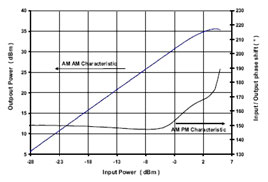
Generally, the nonlinearity of a power amplifier can be characterized by the AM-AM and the AM-PM distortions. The AM-AM distortion occurs as the gain varies when the input power level changes, while the AM-PM occurs when the phase shifts with a change in the input power level.4,5 The AM-AM and AM-PM distortions are illustrated in Figure 1. In modern communication systems, the adjacent channel power ratio (ACPR) is commonly used to characterize the performance of power amplifiers.
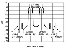
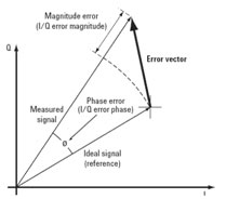
Figure 2 shows an example of ACPR. Another important RF power amplifier specification is the error vector magnitude (EVM), which is a common modulation quality metric and is widely used in digital communication systems, as shown in Figure 3.
Baseband Digital Predistortion System
The nonlinear distortion of the RF power amplifier can be reduced or corrected through linearization techniques, such as the feedback method, the feedforward method, the RF predistortion method, the baseband digital predistortion method, etc. Each linearization method has its advantages and limitations.
Among these methods, the baseband digital predistortion (DPD) technique, with the support of modern digital techniques, can be applied for many kinds of power amplifiers and different kinds of modulated signals. The DPD follows the trend of digitalization and thus will have great potential in the future.
The basic idea of baseband predistortion is to adjust the baseband signal before the modulator and the power amplifier, so that the linearity of the entire system is improved. A simplified block diagram of the entire system, including the PA, ADCs, DACs, modulator and the demodulator, is shown in Figure 4, where F (|Vi|) is the complex predistortion function of the DPD, while G (|Vp|) is the complex gain of the PA and the modulator. When the input signal, Vi, is applied to the DPD, the predistorted signal Vp is obtained. The predistorted signal Vp is then sent to the modulator and the PA, and the PA output signal is Vout. A portion of Vout is coupled out and demodulated to the feedback baseband signal Vf. The relationship between Vi and Vout is

Vout = VPG (|VP|) =
ViF (|Vi|)G[|ViF(|Vi|)|] (1)
Since only a very small amount of output power is coupled to the downconverter and the demodulator, it can be assumed that the feedback baseband signal Vf is linearly proportional to the PA output Vout
Vf ∝ Vout (2)
If the predistortion function F is properly chosen, the product of F and G will be a constant k. Thus, the cascade of the DPD, the modulator and the PA will be an ideal linear transmitting system.
The complex predistortion function F is indexed according to the magnitude of the input complex signal. When a baseband signal is applied to the input of the system, an address is generated, with which the corresponding complex coefficient is obtained.
This look-up table (LUT) method is a useful digital predistortion method. The complex coefficients are generated according to the nonlinear model of the power amplifier. The nonlinear model can be abstracted with an adaptive algorithm and the iteration procedure.
First, a known training signal is sent to the complex gain adjustment module, and is then modulated and up-converted to an RF signal. The digital complex feedback signal is obtained after the power amplifier, down-converter, demodulator and DACs. Second, the digital feedback signal is synchronized with the input training signal by calculating the correlation between the input signal and the feedback signal. Finally, using the adaptive algorithm and the interpolation polynomial method, the complex gain coefficients are obtained.
Several iterations are generally needed to obtain the optimal coefficients, so that the relationship between the initial training signal and the final feedback signal satisfies
Vf = CVi (3)
where
C = complex constant. Since the transmitter input signal is known, any type of signal can be regarded as the training signal, and because the algorithm described above is independent of the type of input signal, the complex coefficients can be updated adaptively.
Hardware and Software Realization

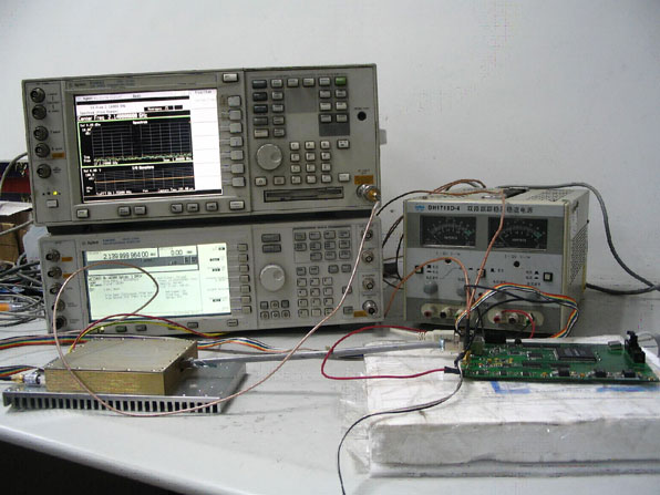
According to the method previously described, an adaptive DPD system based on the complex LUT was developed. The system is composed of two parts: the baseband digital board and the RF board. The baseband board includes a field-programmable gate array (FPGA) for algorithm implementation, a micro control unit, the ADC for obtaining the digital feedback signal, and the DAC for obtaining the analog distorted baseband signal. The RF board includes an RF modulator, an RF demodulator, an RF synthesizer and a PA. The RF modulator and the PA form a complete RF transmitter. The RF demodulator is used for the adaptive algorithm. Figure 5 shows a photograph of the DPD system.
Experimental Tests
Experimental tests were carried out to verify the adaptive DPD system. For simplicity and clarity, a ramp signal was used as the training signal to estimate the nonlinear model of the transmitter. After several iterations, optimal LUT coefficients were obtained.
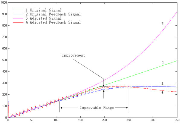
Figure 6 shows the comparison among the original training signal, and the feedback signal before and after the DPD. The original signal (the green line) is a ramp signal. Ideally, the feedback signal should also be a ramp signal.
Due to the nonlinearity of the power amplifier, the original feedback signal (the blue line) is compressed. According to the original feedback signal, the output of the DPD is adjusted to the pink line.

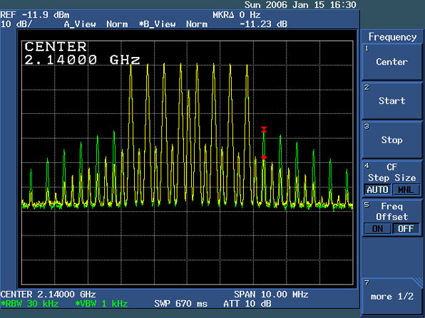
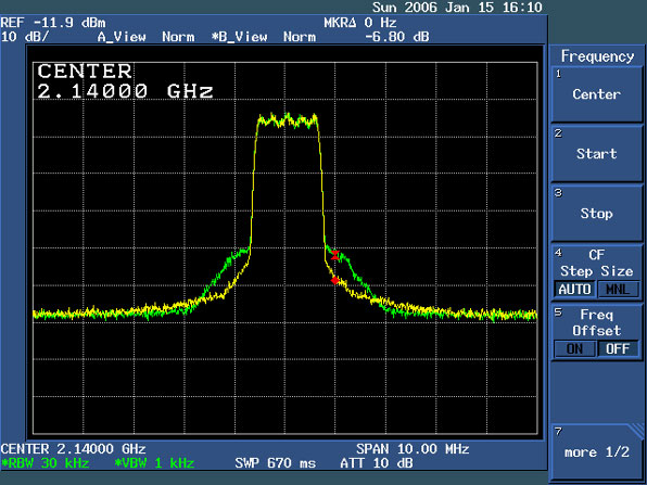
After adjustment, the improved feedback signal (the yellow line) is obtained. Clearly, the adjusted feedback signal is closer to the ideal feedback signal. The improvement of the DPD system can be observed both in the spectral domain and in the time domain. With the DPD system, the IMD products can be reduced significantly, as shown in Figures 7 and 8. The IMD improvement for a two-tone signal is approximately 13 dB, and for an eight-tone signal is approximately 11 dB. For digital modulation signals, the spectral regrowth can be improved greatly, as shown in Figures 9 and 10.
The reduction is 6.9 and 6.8 dB for a WCDMA signal and a cdma2000 signal, respectively.
The ACPR performance is therefore improved significantly, as shown in Figure 11. The improvement in ACPR is more than 6 dB. It is important to notice that this DPD system has a wideband performance and can reduce the power level on both the adjacent and the alternate channels. The DPD system does adjust both the magnitude and phase of the baseband signal in the time domain, so that the modulation accuracy or the EVM performance can also be improved, as shown in Figure 12.
The EVM of a WCDMA signal is reduced from 10.32 to 8.77 percent and the peak code domain error (Pk CDE) is reduced from –31.9 to –34.05 dB.

Conclusion
A baseband digital predistortion system has been developed with a complex LUT, which is updated by the adaptive algorithm based on the nonlinear PA model. According to the experimental results, with the DPD system, obvious improvements are achieved both in the spectral domain and in the time domain for several kinds of input signals.
References
- F. Zavosh, et al., “Digital Predistortion Techniques for RF Power Amplifiers with CDMA Applications,” Microwave Journal, Vol. 42, No. 10, October 1999, pp. 22–50.
- A.S. Wright and W.G. Durtler, “Experimental Performance of an Adaptive Digital Linearized Power Amplifier,” IEEE Transactions on Vehicular Technology, Vol. 41, No. 4, November 1992, pp. 395–400.
- K. Mekechuk, et al., “Linearizing Power Amplifiers Using Digital Predistortion, EDA Tools and Test Hardware,” High Frequency Electronics, April 2004.
- “Guide to Digital Predistortion,” Agilent Application Note, December 2003.
- J.K. Cavers, “Amplifier Linearization Using a Digital Predistorter with Fast Adaptation and Low Memory Requirements,” IEEE Transactions on Vehicular Technology, Vol. 40, No. 4, November 1990.
- M. Shi, M. Chen, L. Zhang and J. Zhou, “A New Baseband Digital Predistortion System,” 2005 Asia-Pacific Microwave Conference Digest.
