
A cross-planar monopole, with an omni-directional radiation in the horizontal plane and a wide operating impedance bandwidth, has been described.2 A cross semi-circular monopole has also been proposed,3 but without a rejected frequency band.
The interference between the UWB and WLAN systems is an important issue4,5,6 for UWB applications.
The demand for band-rejected characteristics of an antenna is rapidly increasing and some studies of band-rejected cross monopole antennas have been published.
A dual-frequency cross-shaped monopole4 was constructed and investigated. Its band-rejected property in the undesired frequency band was observed. Crossed planar monopole antennas5 with single and multiple U slots were also implemented. There are two major techniques to reject a frequency band in cross monopole antennas: One is by using slots, the other by using slits. A broadband UWB antenna, using a cross semi-elliptic monopole with a finite ground plane, was successfully achieved.7 The bandwidth obtained was from approximately 1.85 to more than 12 GHz and a good radiation property was shown. By adding four narrow slits, a 5.25 to 6.40 GHz rejected frequency band was created.

In this article, a novel design of a cross-shaped semi-elliptic monopole antenna with a rejected band is presented and investigated. The band-rejected property is obtained by embedding four L-shaped slits into the lobes of the antenna. The characteristics of the proposed antenna are compared to the cross semi-elliptic monopole antenna with four narrow slits and the crossed planar monopole antennas with single and multiple U slots.5
Antenna Design
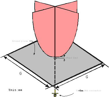
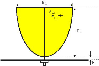
Figure 1 shows the geometry of the cross semi-elliptic disc monopole antenna. The cross monopole is made of 0.1 mm copper sheets, with two semi-elliptic conducting plates located orthogonally above a square ground plane of dimensions G x G x 0.1 mm. The length of the major axis is 2H1 and the length of the minor axis is W1, as shown.

The design rules and measured results for this antenna have been published previously.7 The configuration of the new, band-rejected, cross semi-elliptic monopole antenna is shown in Figure 2. The four L-shaped slits of approximate length D2 + D1 and width S2 = S1 = 2 mm are symmetrically embedded into the cross semi-elliptic disc monopole antenna.
The cross semi-elliptic monopole is composed of four lobes, which are located in the planes along the x- and y-axes. The ground plane, located in the x-y plane, has the dimensions 120 x 120 x 0.1 mm.
When the four L-shaped slits are embedded in the cross semi-elliptic disc monopole antenna, they strongly disturb the current distribution in the specified rejected frequency band.

This results in the band-reject characteristics of the antenna. Since most of the current tends to be concentrated near the curved edge of the lobes of the antenna, the location of the slits, used in the proposed band-rejected technique, will be optimum. The current distribution of this design is more effectively disturbed than that of the finite ground plane cross semi-elliptic monopole antenna with four narrow slits.
7 The effect of this strong disturbance is shown in the antenna gain. The overall length of the proposed narrow slit is approximately equal to (D1 + D2) – (S1 + S2) or approximately 0.22 lc, where lc is the wavelength at the center frequency of the rejected band.

The center frequency is a strong function of the overall length of the slit. The bandwidth of the rejected band is determined by the position of the L-shaped slits. In addition, compared to the cross semi-elliptic monopole antenna with four narrow slits,7 the proposed design has a better gain suppression because the L-shaped slits disturb the current distribution more strongly.
Parametric Studies and Discussion
The parametric study of the proposed antenna offers some helpful information to antenna engineers. The parameters considered include D1, D2 and D3. Through these investigations, an antenna for UWB application can easily be designed.

Different Values of D1
Figure 3 shows the measured return loss for different length D1.
The other parameters are fixed: W1 = 32 mm, H1 = 28 mm, H = 1 mm, G = 120 mm, S1 = S2 = 2 mm, D2 = 8 mm and D3 = 4 mm. As D1 increases, the rejected band moves to a lower frequency. It also shows that the bandwidth of the rejected band is not sensitive to D1.
Different Values of D2
Figure 4 shows the measured return loss with different length D2.
The other parameters include: W1 = 32 mm, H1 = 28 mm, H = 1 mm, G = 120 mm, S1 = S2 = 2 mm, D1 = 10 mm and D3 = 4 mm. As D2 increases, the rejected band also moves to a lower frequency.
It also shows that the bandwidth of the rejected band is not sensitive to D2. The length of (D1 + D2) – (S1 + S2) is approximately equal to the overall length of the slit. It is expected that the rejected band of the proposed design will move to a lower frequency as D1 or D2 are increased.
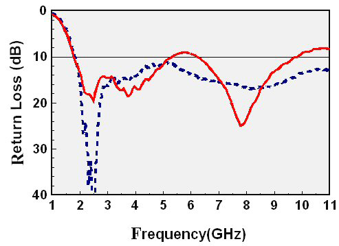
Different Values of D3
Figure 5 shows the measured return loss with different length D3, the other parameters being: W1 = 32 mm, H1 = 28 mm, H = 1 mm, G = 120 mm, S1 =S2 = 2 mm, D1 = 10 mm and D2 = 8 mm. As D3 increases, the center frequency of the rejected band is slightly affected.
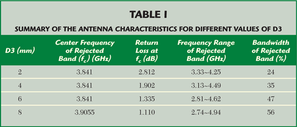
However, the bandwidth of the proposed antenna is strongly affected by the length of D3. When D3 increases, the L-shaped slit is moved toward the antenna feed and the bandwidth of the rejected band is monotonically increased. Table 1 is a summary of the antenna characteristics for different values of D3. It is also observed that the bandwidth of the rejected band varies from 24 to 56 percent, which is suitable for the proposed application.
A Design for UWB Applications
An antenna design for a UWB system has been implemented. The measured return loss of the proposed antenna with dimensions H1 = 28 mm, W1 = 32 mm, H = 1 mm, G = 120 mm, S1 = S2 = 2 mm, D1 = 6 mm, D2 = 4 mm and D3 = 8 mm is plotted in Figure 6 and is compared to a cross semi-elliptic monopole antenna without slots of similar dimensions.7 The rejected band of this proposed antenna is from 5.15 to 6.04 GHz, which fits the requirement of the DS-UWB proposal.8 In other words, this design succeeds in suppressing the interference between the UWB and WLAN systems.
The measured results for the band-rejected antenna proposed show operating bandwidths of 1.85 to 5.29 GHz and 6.3 to 9.8 GHz for a return loss greater than 10 dB. Figure 7 shows the real and imaginary impedances of the proposed antenna.

It is found that the real impedance of the proposed antenna is dramatically increasing within the rejected frequency band, while the imaginary impedance is rapidly changing, leading to the band-rejected characteristics of the antenna.
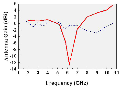
Figure 8 shows the measured radiation patterns of the proposed antenna in the x-y plane at f = 2, 4 and 8 GHz. The x-y plane radiation patterns are almost omni-directional. Figure 9 shows the radiation pattern in the y-z plane. The measured patterns of the proposed antenna are dipole-like radiation, which makes the proposed antenna suitable in practical UWB applications. The measured x-y plane peak antenna gain for the referenced antenna7 and the proposed antenna are shown in Figure 10 over the impedance bandwidth. It is obvious that the proposed antenna with four L-shaped slits significantly affects the x-y plane peak gain within the rejected bandwidth. The measured y-z plane peak antenna gains for the referenced antenna and the proposed antenna over the impedance bandwidth are shown in Figure 11. It is obvious that the proposed antenna with four L-shaped slits significantly affects the x-y and y-z plane peak gains over the band-rejected bandwidth. Compared with the gain of the referenced antenna, the proposed antenna shows a maximum gain drop of approximately 12.2 dBi at 6.2 GHz in the y-z plane and a maximum gain drop of approximately 3.2 dBi at 6.0 GHz in the x-y plane. Therefore, the gain drop over the rejected band of the proposed antenna is significantly improved, compared to the referenced antenna with four narrow slits.7
Conclusion
A band-rejected cross semi-elliptic monopole antenna with four L-shaped slits has been implemented and investigated. The experimental results show that the impedance bandwidth obtained for this antenna design fits the requirements of wireless applications.
The dipole-like radiation patterns over the operating bandwidth are also shown. In addition, the proposed antenna shows a good gain drop within the rejected band, compared to a corresponding cross semi-elliptic monopole antenna with four narrow slits.
7 The proposed design of this antenna is suitable for practical wireless applications. n
Acknowledgment
The financial support of this study by the National Science Council, Taiwan, Republic of China, under contact number NSC94-2213-E-218-006-, is gratefully acknowledged. 
References
- H. Schantz, The Art and Science of Ultra-wideband Antennas, Artech House, Norwood, MA, 2005.
- M.J. Ammann, “Improve Pattern Stability for Monopole Antennas with Ultra-wideband Impedance Characteristics,” 2003 IEEE Antennas and Propagation Society International Symposium Digest, Vol. 2, pp. 818–821.
- P.V. Anob, K.P. Ray and G. Kumar, “Wideband Orthogonal Square Monopole Antennas with Semi-circular Base,” 2001 IEEE Antennas and Propagation Society International Symposium Digest, Vol. 1, pp. 294–297.
- Y. Rikuta and R. Kohno, “Characteristics of Planar and Orthogonal Planar Monopole Antenna with Dual Frequency for UWB System,” 2004 IEEE Antennas and Propagation Society International Symposium Digest, Vol. 1, pp. 171–175.

- W.S. Lee, D.Z. Kim, K.J. Kim, K.S. Son, W.G. Lim and J.W. Yu, “Crossed Planar Monopole Antenna Having a Band-notched Characteristic,” 2005 IEEE Antennas and Society International Symposium Digest, pp. 705–708.
- K.L. Wong, Y.W. Chi, C.M. Su and F.S. Chang, “Band-notched Ultra-wideband Circular-disk Monopole Antenna with an Arc-shaped Slot,” Microwave and Optical Technology Letters, Vol. 45, May 5, 2005, pp. 188–191.
- . W.S. Chen and M.K. Hsu, “The Design of a Finite Ground Plane Cross Semi-elliptic Monopole Antenna for UWB Applications,” Microwave Journal, Vol. 49, No. 5, May 2006, pp. 192–204.
- R. Fisher, R. Kohno, H. Ogawa, H. Zhang, M. McLaughlin and M. Wellborn, “DS-UWB Proposal Update,” Doc.: IEEE 802.15-04/140r3, May 2004.
Wen-Shan Chen received his BS degree in electronic engineering and technology from the National Taiwan Institute of Technology (now known as the National Taiwan University of Technology) and his PhD degree from National Sun Yat-Sen University, Kaohsiung, Taiwan, in 2001. From 2001 to 2002, he was an assistant professor at the Chien-Kuo Institute of Technology, Changhua, Taiwan. He is currently an assistant professor of electronic engineering at the Southern Taiwan University of Technology, Tainan, Taiwan. His research interests include antenna design, RF and microwave circuits.
Mao-Kai Hsu received his BS degree from the China Institute of Technology, Taipei, Taiwan, in 2003. He is currently a graduate student in the department of electronic engineering at the Southern Taiwan University of Technology. His research interests include monopole antennas for wireless communications, especially the cross monopole antenna for UWB applications.