

Microstrip-type directional couplers have several advantages over lumped-element-type directional couplers, such as ease of manufacture, repeatability and low cost. However, the length of the microstrip lines is inversely proportional to the operational frequency. As the operational frequency decreases, the length of the microstrip lines increases.
As a result, it is impractical to implement microstrip designs in the HF range using conventional techniques because of the length factor.
Three-line microstrip directional couplers have been investigated by many authors at microwave ranges.1–3 To this author’s knowledge, however, there has not been a single publication on the design of microstrip directional couplers using multi-layer structures in the HF range.
In this article, the design of a three-line microstrip directional coupler for high power RF applications in the HF range using multi-layer dielectrics is reported for the first time. This is accomplished by designing the directional coupler at a frequency that is higher than the operational frequency and using its forward-coupling slope characteristic to obtain the final design at the operational HF frequency.
The multi-layer dielectric structure that is implemented in this design improves the performance of the directional coupler by effectively increasing the minimum arcing distance between the coupled lines and the main line, which is necessary in high power applications. A three-line microstrip directional coupler is designed and then simulated using an EM simulation tool. The directional coupler is then constructed and measured. The simulation and the measured results are compared and found to be very close.
Directional Coupler Design
The operational frequency of the directional coupler is specified to be 27.12 MHz. This is a common operational frequency for plasma and MRI applications. The forward coupling of the directional coupler is specified to be –24 dB. Teflon is the specified substrate and is chosen because of its cost effectiveness.
The physical length of the standard coupled lines would be impractically long to be realizable as mentioned in the introduction, when the operational frequency is in the HF range. For instance, a quarter-wavelength 50 Ω microstrip on a 100 mil-thick Teflon substrate at 27.12 MHz would be over 80 inches long.
One way to overcome this problem is to design the directional coupler at a higher frequency and use its forward-coupling slope characteristic to have the desired coupling level at the operational frequency.
This reduces the physical length of the directional coupler significantly and gives the desired coupling level at the operational frequency. For this reason, a three-line directional coupler at 300 MHz for a –10 dB forward-coupling level was designed using a method of moment (MoM)-based field solver. A two-layered Teflon dielectric structure was used. Each layer in the multi-layer structure is 60 mils thick. The EM simulation is performed initially to confirm the design and obtain the final physical parameters of the directional coupler. EM simulation results are then verified with the experimental results.
Simulation Results
A method of moment-based EM simulation tool was used to simulate the directional coupler. The forward coupling and the directivity levels of the coupler are shown in Figure 1. The simulation results for the forward coupling and the directivity levels at 27.12 MHz are –24.57 and –20.71 dB, respectively. Based on the simulation results, the forward coupling and the directivity levels are found to be –9.51 and –19.76 dB at 300 MHz, respectively.
Experimental Results
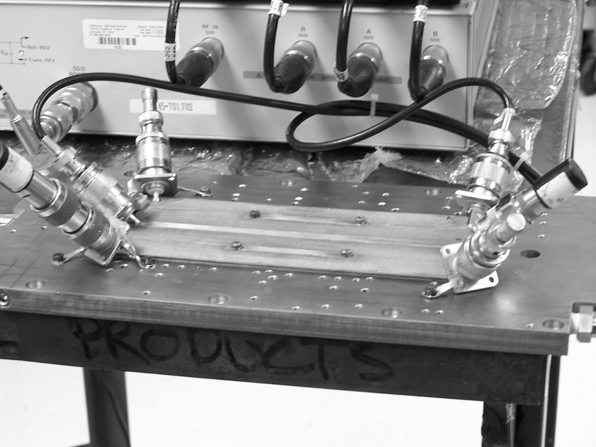
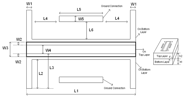
The three-line directional coupler was built based on the final parameters obtained by the EM simulator. A photograph of the coupler is shown in Figure 2. The dimensions of the directional coupler are shown in Figure 3 and given in Table 1.
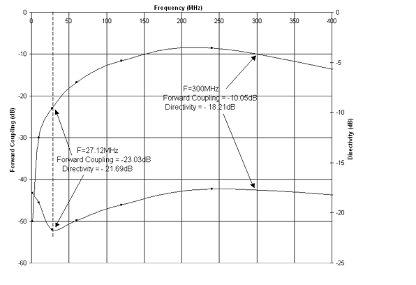
The measured results for the forward coupling and the directivity are shown in Figure 4. The measured results for forward coupling and the directivity levels at 27.12 MHz are –23.03 and –21.69 dB, respectively. The forward coupling and the directivity levels at 300 MHz are found to be –10.05 and –18.21 dB, respectively. There is approximately a four percent error between the measured and the specified forward-coupling levels. The improved directivity response of the coupler seen around the operational frequency is due to the optimization implemented on the structure to get a higher directivity level.
Conclusion
A multi-layer three-line directional coupler for high power RF applications in the HF range has been designed, simulated, built and measured. The results show that it is possible to design microstrip directional couplers in the HF range, if the coupler is designed at a higher frequency and its forward-coupling slope characteristic is used to meet the desired coupler specifications. This design technique significantly reduces the physical length of the directional coupler. In addition, it is shown that a multi-layer structure for microstrip directional couplers in the HF range increases their performance and makes them attractive for high power applications, since a multi-layer configuration effectively increases the minimum arcing distance between the main and coupling lines.
References
- D. Pavlidis and H.L. Hartnagel, “The Design and Performance of Three-line Microstrip Directional Couplers,” IEEE Transactions on Microwave Theory and Techniques, Vol. 24, No. 10, October 1976, pp. 631–640.
- V.K. Tripathi, “On the Analysis of Symmetrical Three-line Microstrip Circuits,” IEEE Transactions on Microwave Theory and Techniques, Vol. 25, No. 9, September 1977, pp. 726–729.
- E. Abdallah and N. El-Deeb, “On the Analysis and Design of Three Coupled Microstrip Lines,” IEEE Transactions on Microwave Theory and Techniques, Vol. 33, No. 11, November 1985, pp. 1217–1222.
 Abdullah Eroglu received his BS degree in electrical and electronics engineering from the University of Gaziantep, Gaziantep, Turkey, in 1996, and his MS and PhD degrees in electrical engineering from Syracuse University, Syracuse, NY, in 1999 and 2004, respectively. He is currently with MKS Instruments, ENI Products, Rochester, NY, working as an RF design engineer. His research interests include RF/microwave circuit design, development of non-reciprocal devices, and wave propagation and radiation in complex mediums, such as plasma.