
The BuNGee Project1 – “Beyond Next Generation Mobile Broadband” – is a project partially funded by the European Commission (EC) to develop an innovative mobile network system with hugely increased capacity over present systems. It forms part of the EC’s Seventh Framework Program of funded or partially funded communications projects. Nine academic and commercial partners are responsible for its development over a period of months until mid-2012.
According to the official BuNGee website, “BuNGee’s goal is to dramatically improve the overall infrastructure capacity density of the mobile network by an order of magnitude (10×) to an ambitious goal of 1 Gbps/km2 anywhere in the cell – thereby removing the barrier to beyond next-generation networks deployment.” The present LTE and WiMAX rates are of the order of 100 Mbps/km2.
BuNGee is intended to exploit new access and backhaul procedures over both licensed and unlicensed parts of the spectrum and develop the concept of intelligent MIMO radio techniques. The Hub Base Station antennas are of a novel construction, which is necessary to exploit the digital processing techniques being developed in parallel by other BuNGee consortium members. They have been designed and developed by the only dedicated antenna partner in the consortium, Cobham Antenna Systems – Microwave Antennas (previously European Antennas), near Newmarket in England.
The main antenna is dual polar, slant linear polarization, with a construction capable of projecting six separate beams of each polarity covering a 90° arc. Thus by positioning four antennas in a square formation at a hub site, complete 360° coverage is achieved using 24 dual-polarized beams in total.
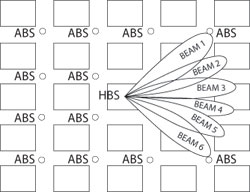
Fig. 1 Typical "Manhattan Grid" configuration showing the single Hub Base Station (HBS) and the Access Base Stations (ABS).
The multi-beam antenna itself is designed to produce six individual beams each with a half-power beamwidth of 15°, such that each pair overlap at the half-power point, which is considered sufficient to provide contiguous coverage over the complete 90° sector. Figure 1 shows a single Hub Base Station (HBS) antenna in the middle of a typical urban “Manhattan Grid” configuration, showing the 90° azimuth spread of six beams. Three further antennas will be installed at the center of the square to provide the remaining 270° required for full coverage. The Access Base Station (ABS) antennas are situated below roof level at the corner of each block.
The whole antenna array comprises eight high gain sector antennas, which are spaced a half-wavelength apart. This spacing provides reduced azimuth sidelobe levels when the sectors are phased together to provide a slewed high gain beam. The individual sectors have been designed to provide a 110° azimuth beamwidth. Each sector is composed of eight tiers of elements spaced about 0.7 wavelengths apart to provide the required elevation pattern.
In order for the six narrow (15°) high gain beams to be formed to cover the 90° arc, two (8×8) Butler matrix beamforming devices2 are used to feed the separate ports of each antenna. By a mechanism of fixed phase shifters and couplers the Butler matrices provide defined sets of phases into each of the eight antenna elements, which results in two sets of eight “skewed” beams. Note that only the inner six of these beams are used to cover the 90° area required for the defined architecture.
The proposed multiple input multiple output (MIMO) radio system feeds each of the six pairs of (dual slant 45°) beams into the matrices through a total of twelve separate inputs. A potential further system benefit can be achieved by “amplitude weighting,” which requires the outer antenna ports to be attenuated. Using this technique, although the gain of the main beams will be slightly lower, the azimuth sidelobes are further reduced giving an improvement in relative sidelobe level, which may result in greater system efficiency.
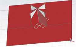
Fig. 2 Modeled individual slant 45° cross-dipole element for Hub Base Station antenna.
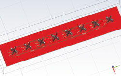
Fig. 3 Modeled eight-element single tier elevation array.
The Single Element and Sector Array
The antenna element, originally modeled in a commercial simulation software package, is based on a single cross-dipole assembly, etched on a standard PCB substrate. The dipoles, in this case optimized to work at a center frequency of 3.5 GHz, are physically interlocked and soldered to a motherboard in a configuration that provides a slant dual polar beam (see Figure 2). In the model, the tracks cross over, using a surface bridge. The final design uses plated-through holes to short bridging tracks on the underside of the board. High sector gain requires eight sets of these assemblies to be fed in phase through a stripline feed to create the fundamental (110° azimuth) sector antenna, which forms the basis for the array. Each dipole pair is mounted on the motherboard spaced 0.7λ apart; the interconnecting tracks of one polarity passing via plated-through holes to short tracks on the underside of the motherboard at the points of crossover. Although the underside of the motherboard has a continuous ground plane, this is relieved locally to accommodate the bridging tracks. To maintain phase fidelity, the tracks of the opposite polarity, which remain on the topside of the motherboard, are lengthened to provide the same electrical length and compensate for these diversions (see Figure 3). The positions of the feed tracks dictate the phase to each element pair and thus the down-tilt; the number of elements controls the gain and the elevation beamwidth.
The 110° HPBW sectorpattern produced by an individual dipole pair, even when combined into the single sector using eight elements, provides the basis for the overall pattern to be achieved with the final array. In this formation, the elevation beamwidth has been reduced from a single element of 110° to 10° through the “array-factor.” By varying the amplitude and phase to each element pair in the vertical array, it is possible to introduce features to the elevation pattern such as electrical (down) tilt, sidelobe-suppression and null-fill, which may be beneficial to the system. These elevation pattern parameters have no effect on, and are independent of, the multiple azimuth beams.
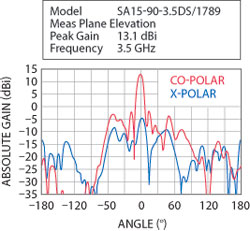
Fig. 4 Measured elevation pattern for eight-element single tier array +45° port (red), the cross-polar signal (blue) are better than 15 dB below the co-polar pattern.
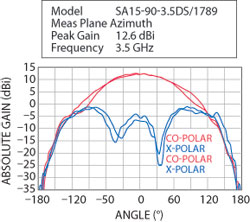
Fig. 5 Measured azimuth pattern for an eight-element single tier sector array.
In this antenna, the down tilt is a nominal 2° across the band of interest, that is 3.4 to 3.6 GHz, with an elevation beamwidth of 10° at the half-power point (see Figure 4). The gain is a function of beamwidth; the more elements in parallel, the higher the gain and thus the narrower the elevation beamwidth. Figure 5 shows the measured azimuth patterns for the eight element single tier sector array, with the +45° and −45° polarizations (in red) superimposed at midband. The two polarizations overlap very well over the center 90° over which the six narrow beams will be arrayed. The cross-polar signals (in blue) are better than 15 dB below the co-polar signals over the center 90° sector.
Multi-beam Azimuth Array
The next step was to use the model of the single element, as modified by iterations of the design, to determine the horizontal spacing of the single dipole pair and the fixed phase shifts necessary across eight elements to provide the “steer” for the beams in the right directions. It remained necessary to cover the 90° arc with six equal (15°) beams, while maintaining the patterns shapes and without introducing high azimuth sidelobes. The principal requirement from the system is that the nearby beams retain a high level of isolation from each other, by becoming narrower and of course benefitting from the higher gain that goes with reducing the beamwidth. This would allow a high level of frequency re-use needed for the required data rates.

Fig. 6 Modeled single tier azimuth array.
The modeling showed that half a wavelength (λ/2) spacing of the element with relevant phase-shifts would provide optimum results. The element had been designed such that this close proximity of adjacent dipoles (in the 45° configuration) would not have any effect on the return loss or pattern fidelity, which was critical for the success of the array. A set of single cross-dipole elements was fixed to a motherboard in a horizontal array to demonstrate the beam-form principle (see Figure 6). Unlike the elevation array which only has two terminations, −45° and +45°, the azimuth array has 16 because all the dipoles are independently fed, although in tests only eight of one polarization were used. Like the elevation array, a prototype was built up and tested in Cobham Antennas’ anechoic chamber, which, after processing, allowed full far field radiation patterns to be created.
Early modeling showed a possible need to use dummy elements at either end to further control beam direction, which in practice proved unnecessary. This discovery paved the way to eventually develop the 8 × 8 element array with all the elements electrically functional.
The Butler Matrix
The Butler matrix is a passive (unpowered) beamformer, the principles of which were first described by Butler and Lowe2 in 1961 and depend on achieving even increments of phase shift at the outputs, according to which one of successive inputs is fed.
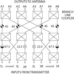
Fig. 7 Typical Butler matrix showing the 90° branch line couplers and interconnections showing phase shift in each combination of connections.
The beamformer specified for BuNGee is designed using stripline technology and proprietary crossover circuitry (see Figure 7). It uses six inputs and eight outputs. Using Input 1 causes a phase shift of 22.5° per output port, 67.5° per output port when using Input 2, and 112.5° per output port when connected to Input 3. The three remaining input ports produce phase shift in the opposite direction, that is −22.5°, −67.5° and −112.5°, respectively. When connected to the azimuth array, using accurately phase-matched cables, the beams can be “steered” in six 15° increments from 37.5° to the left to 37.5° to the right simply, according to which of the six inputs has been activated. When the half-power beamwidth of 15° per beam is taken into account, it gives the desired azimuth coverage of 90°. One Butler matrix is used for each antenna polarization, so two are fitted per complete array.
Figure 8 shows the Butler matrix connected to the prototype azimuth array using eight carefully phase-matched cables and positioned in Cobham Antennas’ near field spherical test chamber. Using this with dedicated software allows a complete sphere of far field data to be extracted and, as each antenna test takes about 20 minutes or less, it is practical to conduct many tests in a working day.
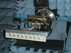
Fig. 8 Single tier azimuth array and fixed-phase beamformer (behind, connected with phase matched cables).
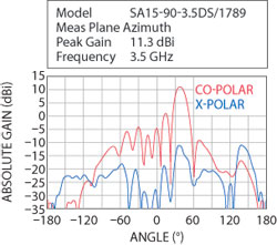
Fig. 9 Measured mid-band azimuth pattern for eight-element single tier array –45° polarization showing 37.5° beam steering.
The plot in Figure 9 was extracted from one of these tests, showing clearly the predicted 37.5° azimuth beam shift, when a signal was applied to “Input 3, Right Hand” on the Butler matrix. Many of the modeled parameters of the final antenna are demonstrated as measured. The beamwidth is close to the predicted 15°, in this case 15.8°.The main sidelobe is practically 12 dB below the main beam and the cross polar level comfortably exceeds the −15 dB minimum specified.
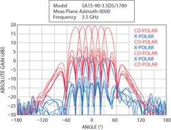
Fig. 10 Overlaid beams from –37.5° to +37.5° over a 90° azimuth spread using the 8×8 array.
The Complete Antenna
Having combined the principles of the cross polar topography and the Butler matrix, it was possible to develop the 8×8 element antenna. The simulated model was interpreted into a practical array, using the same design features of the original elevation and azimuth tiers. The model predicted a theoretical peak gain of 19 dBi with the essential 15 half-power beamwidth in azimuth and 10° in elevation. However, some losses were to be expected in the Butler matrix and phase matched cables, but the assembly had proven the principles.
The superimposed beams measured in one polarization are demonstrated in Figure 10. The 90° azimuth spread, from −45° to +45° can clearly be seen with the 3 dB (half-power) points coinciding with the handover points between adjacent beams. Near 0° the gain is 19 dBi and even at the beam extremities never drops below 17.5 dBi.
Control of Azimuth Side-Lobes Through Amplitude Weighting
The highest first sidelobe for any beam falls at least 12 dB below the main beam and typically the level is nearer 13.5 dB, but even this can be improved upon if amplitude weighting is introduced. This is a technique using low value series attenuators in line with the Butler matrix outputs to the antenna. The two central columns are typically left unattenuated, but to preserve phase fidelity 0 dB attenuators are fitted of the same electrical dimensions as the attenuators connected to the outer tiers. Working outwards the next two columns may either have 0 dB or perhaps 1 dB attenuators connected, while the remaining tiers have progressively larger value components fitted such that the greatest attenuation occurs on the outermost extremities of the array. While the effect is almost unnoticeable in the elevation cut, except for a slight decrease in overall gain, the sidelobe levels in azimuth are significantly reduced relative to the loss in gain of the main beam.
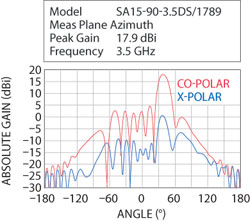
Fig. 11 +37.5° azimuth beam using the 8×8 array without amplitude taper.
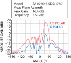
Fig. 12 +37.5° azimuth beam using the 88 array with 0, 0, 2 and 5 dB attenuators.
Figures 11, 12 and 13 illustrate the progressively lower sidelobe levels as the amplitude weighting is increased on the same antenna array. For a drop in main beam gain of 2 dB, an improvement of 5 dB in relative sidelobe level can be achieved. This may be a valuable trade-off and option for the system designers to use, although there comes a point, of course, beyond which the drop in main beam gain is undesirable, which dictates the limit.
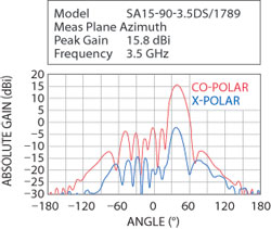
Fig. 13 +37.5° azimuth beam using the 8×8 array with 0, 1, 3 and 5 dB attenuators.
Antenna Deployment
The Hub Base Station antenna described above is intended to be deployed within an urban “Manhattan Grid” formation, affording coverage through 360° by virtue of positioning four antennas just above roof-top height, each covering a 90° sector, and working in the 3.4 to 3.6 GHz band. These communicate with line-of-sight, or virtually line-of-sight dual-slant linear Hub Subscriber Station antennas, sited below rooftop within the grid and sharing their location with (different frequency) Access Base Station antennas. These, in turn, point up and down streets to communicate with (personal) mobile terminals. The installations in both cases are intended to be cost effective. Multi-beam technology will be much more efficient to install where antenna mounting considerations, such as weight, wind speed, and thus mast/roof-top rental are paramount. Re-use of the spectrum for this dense data-rate means lower license fees for operators per bit of data transmitted. Below-rooftop deployment and co-location of the Hub Subscriber Antenna/Radio and Access radio/antennas reduces the cost of installation. Carefully controlled antenna beamwidth and intelligent MIMO techniques, (being developed separately within the BuNGee project), as well as judicious positioning of neighboring Hub Base Station multi-beam antennas, reduce interference within the system, increasing signal to noise ratios. A nominal peak gain per antenna of 19 dBi, while providing useful penetration also produces a well-defined beam set with the extra advantages of dual polar technology at both ends of the link (2×2 MIMO).
Summary
The multi-beam antenna, developed by Cobham Antenna Systems to be deployed in the BuNGee communications project, is a novel approach to dual polar, beamforming technology. The use of a Butler matrix to produce a set of beams spanning a wide sector allows for a significant increase in the data throughput when compared with a wide beam antenna of sufficiently high gain, and is more compact than having the equivalent of six separate narrow beam antennas. This rewards the user with reduced installation and deployment costs, while being able to control individual beams where needed.
References
2.Butler and Lowe, “Beam-Forming Matrix Simplifies Design of Electronically Scanned Antennas,” Electronic Design, Vol. 9, April 1961, pp. 170-173.