
Presently, the trend in satellite communication is focusing on high frequencies with wider user bandwidths. Directional couplers are an integral part of onboard as well as ground applications, either for combining or splitting power. Planar directional couplers, using coupled microstrip lines, are commonly used for different coupling values.1 Couplers can be either three- or four-port networks. Four-port couplers are preferred, due to their inherent advantage of better matching, isolation and reliability. Backward wave couplers are classified as four-port networks.
The major advantage of using backward wave directional couplers is that the input signal port and the coupled output signal port are on the same side and their implementation in a system configuration becomes easier. The major constraints, in the realization of planar directional couplers, are size and bandwidth requirements.
A traditional technique for achieving broadband is to increase the number of coupled sections, each a quarter-wavelength long. The coupling coefficients for each section are calculated using standard equations.² In this article, a proposed three-section directional coupler is investigated and compared with a standard coupler.
The proposed coupler is designed using one-twelfth wavelength-long coupled sections, along with modified coupling coefficients. The design and development of a 10 dB coupler at Ku-band, in the frequency range 13 to 18 GHz, is described. A standard three-section design was also carried out and compared with the proposed approach. This novel approach gives a size reduction of at least 66 percent, along with improved performance characteristics. Symmetry is maintained for ease of implementation. The one-twelfth wavelength coupled sections are analytically inexact, but practically exact for engineering applications, as shown here.
Analysis and Derivation
The traditional design approach for a directional coupler uses binomial, Chebyshev or Klopfenstein tapering,² along with impedance transformations for the different sections. A broad bandwidth can be achieved by using an increased number of sections along with the Chebyshev transformation. A three-section coupled-line structure, each a quarter-wavelength long and with different coupling coefficients, is the most widely used. The solution for the standard design, using Fourier analysis for the Chebyshev transformation, gives rise to the following coupling coefficients for a 10 dB coupler.4

where L = λ/4 for each section
This shows that the coupling at the outer section is loose compared to that at the middle section. Figure 1 shows the proposed design of a three-section directional coupler and its equivalent single line model. This model is applicable for multiple sections with the condition that ZoeZoo = Z02 is maintained throughout the section.

The input impedance at A is given by

These equations give rise to transcendental equations, which, with some assumptions, can be solved for Z1, Z2, Z3, x1, x2, x3 using nonlinear software.

Solution
This solution will be in the form

The nonlinear solution for Equations 1 to 3 gives rise to Z1 = 70 ω, Z2 = 59 ω for x = 0.083 λ0. The proposed design uses the three-section coupled line structure, with one-twelfth wavelength line, using the single line model, and the impedances obtained by solving the transcendental equations.
Broadbanding Approach

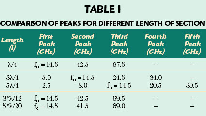
The following data has been collected via simulation to validate the approach for the given topology. Table 1 shows the analysis results for sections of different line lengths to validate the approach. The table shows that, by using three λ/4 sections with the center frequency at 14.5 GHz, the second peak appears at 24.5 GHz, the next at 34 GHz and so on. However, by using three λ/12 sections with the center frequency again at 14.5 GHz, the second peak appears at 42.5 GHz, the next at 69.5 GHz and so on. For the same amplitude in both cases, it is obvious that three λ/12 sections will provide more bandwidth than three λ/4 sections, thereby providing broadband characteristics.
The slight change in the frequencies of the second and third peak, when using five λ/20 sections, is due to the slight change in wavelength, because of impedance mismatch between the sections. The approach is to use odd number of multiple (N) sections each of length λ/4N, so that the total length is always Nλ/4N = λ/4, and hence the fundamental peak alone is dealt with, solving the amplitude criticality problem.
Design Methodology

The number of sections is chosen to be three for both the standard as well as the proposed design. The length of each section of the standard coupler is made to be &lambda 0/4 and the couplings obtained being –8.07 dB (for the center section) and –28 dB (for the outer section).
The coupling of the outer sections is loose, while that of the center section is tight, resulting in a –10 dB-coupled output over a broad frequency range. The circuit was fabricated on a 10-mil thick alumina substrate (ε r = 9.8). The line dimensions corresponding to the coupling are shown in Figure 2.
The proposed three-section coupler has been designed using three λ/12 coupled sections, the coupling coefficients being 0.131 and 0.176 (using Fourier analysis), which corresponds to couplings of –8.5 dB (outer sections) and –10 dB (center section). Here, too, the coupling coefficient of the outer section is different from that of the middle section. The difference between the standard and proposed designs is in the tightness of coupling.

The proposed design has tight coupling in the outer sections while incorporating loose coupling in the middle section, which is contrary to the standard design. The corresponding dimensions, along with the spacings, are shown in Figure 3.
Simulation
Simulation was carried out using Linmic software,8 which is basically an electromagnetic analysis tool. The software tool generates the look-up tables at the desired frequencies, taking into account the discontinuities as well as line losses and parasitics and these are used in the simulation. These results are further verified using electromagnetic simulation with Momentum from ADS. The corresponding widths and lengths are found using standard formulae.4,5 The symmetry of the middle section is maintained by adjusting the line dimensions. The impedance at the outer section is maintained at 57.37 Ω instead of 53 Ω, after optimization.
Experimental Results
The fabricated circuit has been tested using a network analyzer (8510C from Agilent). Figure 4 shows the measured and simulated coupling, comparing the standard design with the proposed design in the 13 to 18 GHz frequency range. Figure 5 shows the comparison of the insertion loss, which is better than 2 dB for the proposed design over the wideband range.
The connector losses as well as the conductor and radiation losses are included in the measurement. Figure 6 shows the isolation between ports, which is better than 25 dB. A return loss better than 18 dB is achieved over the entire frequency band. These measurements were carried out with a standard jig of dimensions 30.2 ¥ 12 mm. For the circuit to fit within the jig dimensions, the 50 Ω line lengths have been extended by 10 mm at each port, resulting in increased line losses.6 The circuit size is approximately 2.1 ¥ 0.88 mm. Figure 7 is a photograph of the proposed coupler circuit.

Conclusion
The proposed coupler shows a close agreement between the simulated and measured results. The repeatability of the structure was verified. This approach is different from the traditional approach where the middle section is tightly coupled and the outer loosely coupled.
An added advantage is a considerable size reduction without compromising the other characteristics. This design approach can be easily extended to higher frequencies for both MIC and MMIC configurations. Because of the present fabrication limitations in MIC, due to etching difficulties to achieve the spacing and tight coupling specifications, only a three-section coupler could be designed and fabricated. However, in the future, as the fabrication limitations are eased, couplers using five or even seven sections for tight coupling can be designed and developed using this novel approach.
References
1. G. Matthaei, L. Young and E.M.T. Jones, Microwave Filters, Impedance-matching Networks and Coupling Structures, Artech House Inc., Norwood, MA, 1980.
2. D.M. Pozar, Microwave Engineering, Second Edition, John Wiley & Sons Inc., New York, NY, 2004.
3. G.D. Vendelin, A. Pavio and U.L. Ulrich, Microwave Circuit Design Using Linear and Nonlinear Techniques, John Wiley & Sons Inc., Somerset, NJ, 2004.
4. T.C. Edwards, Foundations for Microstrip Circuit Design, John Wiley & Sons Inc., Somerset, NJ, 1981.
5. E.H. Fooks and R.A. Zakarevicius, Microwave Engineering Using Microstrip Circuits, Prentice Hall PTR, Upper Saddle River, NJ, 1990.
6. V. Vinayakarohit, K. Singh and R. Ramasubramanian, “Analysis of Coupling Deviation in Broadband Backward Wave Directional Coupler at Higher Frequencies,” accepted for oral presentation at INCMARS, India, 2006.
7. Y.L Chow and K.L Wan, “A Transformer of One-third Wavelength in Two Sections– For a Frequency and its First Harmonic,” IEEE Microwave and Wireless Components Letters, Vol. 12, No. 1, January 2002, pp. 22–23.
8. Linmic+/N 6.3 User Manual, AC Microwave, Aachen, Germany.
| |