
The next generation of mobile communication systems will provide a wide variety of new services, from high quality voice to high definition video and high data-rate wireless channels. Moreover, the systems will provide combined services, including the established wire and wireless communications and broadcasting networks. In order to support these services, a wide frequency spectrum will be assigned. The base station power amplifiers for the next generation systems will therefore have to cover a wide instantaneous signal bandwidth, together with a highly linear amplification. However, the wideband signals may cause severe memory effects and nonlinearities in the power amplifiers.1
The memory effects are defined as changes in the amplitude and phase of the distortion components, due to the previous signals. The simplest method for characterizing them is to use a two-tone signal.1–4 The two-tone signals, with varying tone spacing, are applied to an amplifier to measure the distortion components. If the distortion characteristics are identical, regardless of the tone spacings, the amplifier can be expected to be memory-less and to operate properly for wideband signals. Therefore, the memory effect becomes a very important design consideration for wideband base station power amplifiers. It is also the limiting factor for the cancellation of distortion when linearizing a power amplifier (PA) by predistortion techniques.2,5,6 Many previous authors have tried to analyze the memory effect or reduce it.1,4,7,8 The effect is still a big problem for the current base station power amplifiers and is significant even for amplifiers for the universal mobile telecommunications system (UMTS), which has only a 20 MHz signal bandwidth. The objective of this work is to minimize the memory effect of a base station PA and to realize a linear power amplification of a 100 MHz bandwidth signal, which is very important for the next generation PAs. First, the memory effect is analyzed using a simple LDMOS model1,9 and then a detailed simulation is carried out using Freescale’s MRF5S21090 LDMOS model. The analysis and simulation show that the drain envelope impedance is the most important factor for reducing the memory effect and nonlinearity. A new matching topology is proposed for minimizing the drain and gate envelope impedances. The matching topology consists of a series LC circuit for shorting the device at a low frequency while maintaining a matchable impedance at the operating frequency. The circuits are connected to the gate and drain terminals, rather than to the bias lines, since the circuit can produce a very low impedance, not limited by the quarter-wavelength bias line. For the experimental demonstration, based on the analysis and simulation, a power amplifier was implemented at a 2.14 GHz center frequency and tested using two-tone and multi-carrier down-link wideband code division multiple access (WCDMA) signals. The amplifier, with the reduced envelope impedances, provides drastically reduced memory effects and very linear amplification performance for wideband signals.

analysis for im3
A general metal-oxide semiconductor (MOS) transistor is a four-terminal device, the terminals being gate, drain, source and bulk, and the voltages in the transistor are either referred to the source or to the bulk. In the case of a laterally diffused MOS field-effect transistor (LDMOSFET) used in this work, the voltage between the source and the bulk, vbs, can be neglected because they are tied together. The drain current is described as a function of the gate-to-source voltage, vgs, and the drain-to-source voltage, vds, and the AC drain current, up to the third-order nonlinear term, can be expressed by the following third-order power series1,9


where the nonlinear coefficients are defined in Table 1.

In order to extract the third-order intermodulation distortion (IM3) level from Equation 1, a FET model is adopted, containing nonlinear Cgs, gm, g0 and Cds. The gate-to-drain nonlinear capacitance, Cgd, has been excluded to simplify the analysis. The nonlinear components can be replaced by linear components and corresponding distortion current sources.1,9 The linearized model is shown in Figure 1, which contains Norton’s equivalent circuit for the input terminal and three nonlinear current sources, iNL, Cgs, iNL,gm and iNL,g0&Cds. Notice that the nonlinear current sources from g0 and Cds are combined in one source. vgs and vds are written as functions of frequency as
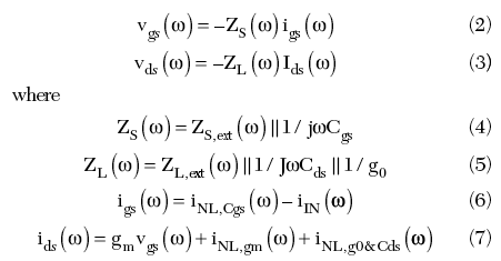

In Equations 6 and 7, the input current, iIN, has only a fundamental signal component but the nonlinear currents, iNL, have no fundamental component. If an equal power two-tone input signal is applied to the amplifier, from Equation 1, the upper IM3 (IM3U) drain current is found to be
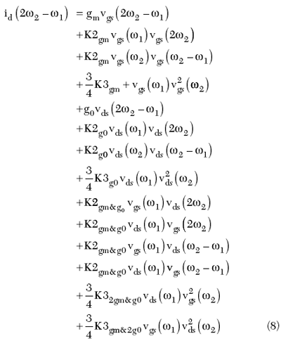

The lower IM3 (IM3L) current is identical, but ω1 and ω2 are exchanged and the (ω1–ω2) term is the complex conjugate of (ω2–ω1). Among the fourteen rows of Equation 8, the values of the first, fourth, fifth, eighth, thirteenth and fourteenth rows are not controllable by a matching circuit because the in-band impedance is fixed by the optimum matching point. The values of the remaining eight rows are controllable since they are functions of the gate envelope (third and twelfth rows), gate second harmonic (second and tenth rows), drain envelope (seventh and eleventh rows) or drain second harmonic (sixth and ninth rows) voltages, which are dependant on the harmonic impedances. For convenience, hereafter, the term ‘harmonic’ is applied to the ‘second harmonic’ (2ω1 and 2ω2) components and separated from the term ‘envelope’ for the (ω2–ω1) frequency component. The memory effect is generated by the controllable terms and to reduce them, the envelope and second harmonic voltages should be reduced to zero by proper terminations. Conventionally, the short is provided at the bias line after a quarter-wave transmission line. In this case, a wideband short is difficult to achieve, since the dispersion of the line limits the achievable minimum impedance level. Thus, the short should be provided at the gate and drain directly without passing through a quarter-wave line. The termination was achieved by using a simple series LC circuit as will be shown in the following sections.

Out-of-band Impedance Limitations
In this section, the realizable lower limits of the impedances at the second harmonic and envelope frequencies are investigated. This study provides the design guideline for the power amplifier with reduced memory effect.
Ideal Situations
Consider a signal with a center frequency fo and bandwidth (fU–fL). The signal distribution is shown in Figure 2, together with the envelope and second harmonic signals. It is assumed that


An ideal matching topology for the output terminal of the FET model is shown in Figure 3. The input matching circuit will be identical to the output one. The figure includes the envelope and second harmonic trap circuits as well as an optimum matching circuit for the fundamental signal. This circuit topology is beneficial for the termination of the harmonic voltages compared to the conventional termination at the bias line, since the impedance dispersion caused by the quarter-wave bias line is eliminated. However, the circuit effectively adds up a reactive impedance at the fundamental frequency and should be designed properly. In order to have impedances of the same magnitude at both frequency edges, 2fL and 2fU, the second harmonic trap circuit, L2 and C2, must resonate at ![]() That is
That is
![]()
If the envelope trap and fundamental matching circuits have fairly high impedances at the second harmonic frequency, the output load impedances for the second harmonics, ZL,ext(2fU) and ZL,ext(2fL), are complex conjugate and their magnitudes are

![]()
As expected, the impedances are related to the inductance and signal bandwidth.
Next, a very large capacitor Ce is needed to short the envelope signal. Again, the second harmonic trap and fundamental matching circuits are assumed to have fairly high impedances at the envelope frequency. Then the magnitude of ZL,ext(fU–fL) is given by
![]()
From Equations 11 and 12, it can be expected that the envelope impedance, ZL,ext(fU–fL), is one half of the second harmonic impedance, ZL,ext(2fU), for the same magnitude of Le and L2. Finally, the optimal fundamental signal matching is achieved by
![]()

where ωL ≤ ω ≤ ωU. If the impedances of the envelope and second harmonic trap circuits at the fundamental frequency are extremely small, it may be impossible to match it in practice. Such a matching problem will restrict the values of Le, L2 and C2. Thus, the lower limits of the realizable second harmonic and envelope impedances are determined.
Practical Situations
Since a base station PA designer generally uses a packaged transistor, one cannot avoid the inductive effect of the bond-wires between the transistor die and the package lead-frame. The bond-wire inductance may give a certain advantage, such as stabilization of the device and increase of the usable bandwidth, when it is used together with an internal matching circuit. However, it obviously acts as an obstacle in controlling the envelope and harmonic impedances. For this work, the packaged MRF5S21090 LDMOSFET manufactured by Freescale was chosen. The transistor is composed of two 45 W cells and is able to deliver 90 W peak envelope power (PEP). The equivalent circuit with the internal matching of a 45 W cell is shown in Figure 4. At the envelope frequency, the capacitors for the internal matching can be ignored and thus the external envelope impedance is changed according to frequency by just the series bond-wire inductors, Lg1 and Lg2 for the gate and Ld2 for the drain. The impedances at the envelope frequency for the input and output, ZS,ext (fU–fL) and ZL,ext (fU–fL), are then given by


On the other hand, for the second harmonic terminations, the gate and drain external matching impedances outside the package, Z'S,ext and Z'L,ext, are given by

Equations 16 and 17 can be realized easily by a harmonic matching circuit including the series L2C2 resonant circuit, because it has a narrow fractional bandwidth contrary to the wide bandwidth of the envelope signal. For the implementation of the envelope termination, a very large capacitor, such as a large tantalum capacitor, with a rather small inductor should be used. The impedance level is limited by the inductors as shown in Equations 14 and 15. Therefore, the envelope is harder to terminate than the second harmonic and the envelope components can be more important than the second harmonics in linearity as well as memory effect. In a practical sense, however, one cannot guarantee that the envelope trap and fundamental matching circuits have fairly high impedances compared to the second harmonic impedance. As a result, in the envelope trap circuit, a simultaneous matching for the fundamental signal and second harmonic is needed. If the values of the internal matching components are not exactly known, it is very difficult to design the termination circuits. Thus, the circuit has been optimized experimentally for a low memory effect and high linearity, focused on the envelope signal.
Simulations

To show the contributions to the memory effect from the gate and drain envelope components, the MRF5S21090 LDMOS model has been simulated using the Advanced Design System version 2004A (ADS2004A) for two-tone signals with a 2.14 GHz center frequency and tone spacings of up to 100 MHz. Figure 5 shows the circuit diagram for the simulation. In the simulation, a high voltage tantalum capacitor for the envelope trap has been selected and its scattering parameters were extracted with a network analyzer and used to support the practical implementation. The tantalum capacitor has a capacitance of 10 μF, which is large enough to short the envelope signal up to 100 MHz and also has parasitic frequency-dependant resistive and inductive components. The measured impedances of the tantalum capacitor are 0.15 + j0.75 Ω and 0.84 + j15.7 Ω at 100 MHz and 2.14 GHz, respectively. The parasitic inductive impedance, which is approximately 1.2 nH, was used for blocking the fundamental signal instead of Le. Of course, the inductance should be resonated out by the fundamental matching circuit. It should be noted that the tantalum capacitor, used for the memory effect control, is on the matching circuit, not on the bias line. The gate and drain bias voltages are supplied through the quarter-wave transmission lines which are used to design the conventional narrow-band PA. The characteristic impedances of the lines are 50 Ω and the bias voltages are VGG = 4.063 and VDD = 27 V, respectively. The amplifier operates in class-AB mode with a quiescent drain current of 850 mA.

In order to investigate the effect of the tantalum capacitors, the simulations have been performed for four cases: (1) without the tantalum capacitors; (2) with the tantalum capacitor on the gate only; (3) with the tantalum capacitor on the drain only; and (4) with the tantalum capacitors on both the gate and drain. In all cases, the input and output matching circuits have been optimized to have the same fundamental impedances, ZS,ext (2.14 GHz) = 2.08 –j3.54 Ω and ZL,ext (2.14 GHz) = 2.15 –j2.0 Ω, and for a gain flatness within 0.2 dB over the 100 MHz bandwidth and high linearity for a two-tone signal with 1 MHz tone spacing. The simulation results for the two-tone signals are shown in Figure 6. The IMD3 (power ratio of IM3 to the fundamental signal) has been plotted as a function of the average output power and the two-tone spacing. The output power has been swept from 30 to 46 dBm in 1 dB steps for tone spacings of 1, 5, 10, 20, 30, 40, 60, 80 and 100 MHz. The red and blue lines represent the upper and lower limits of IMD3 (IMD3U and IMD3L), respectively. The simulation results show that the proposed PA of case 4 has a drastically reduced memory effect and an improved IMD performance for all tone spacings compared to the conventional one. Thus, it is clear that the envelope component is more important than the second harmonic for the device, since only the envelope has been controlled. The following additional information can be obtained:

• For a narrow-band signal, the quarter-wave transmission line can provide sufficient short for the envelope signal and the memory effect is not important.
• For a medium-band signal, the drain envelope voltage is the dominant component for the memory effect and linearity.
• For a low power and wideband signal, the gate envelope voltage is more important than the drain one. It may be due to the larger multiplication factor than for the drain envelope.
• For a high power and wideband signal, the drain envelope voltage is more important than the gate voltage but both the gate and drain envelope voltages should be controlled to reduce the memory effect and nonlinearity.

As a result, the best way is to minimize both the gate and drain envelope impedances.
Experimental Results
Wideband Performance Test Using Multi-carrier WCDMA Signals
For experimental demonstration, two PAs have been implemented, with and without the tantalum capacitors (cases 1 and 4), at 2.14 GHz using the MRF5S21090 LDMOS transistors and RF35 printed circuit boards. The PAs have been optimized to have similar performance in gain flatness and linearity to a down-link WCDMA 1FA signal at the same bias point, VDD = 27 V and IDSQ = 850 mA. Figure 7 shows the measured small-signal gains and power spectral densities (PSD) at an average output power of 40 dBm. The drain efficiencies of the two amplifiers are nearly the same, approximately 18.5 percent at 40 dBm. The PAs deliver flat gains within 0.2 dB over a 100 MHz bandwidth and adjacent channel leakage ratios (ACLR) of approximately –38 dBc.

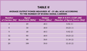
Like for the simulation, the two PAs have been tested for the two-tone signal. Figure 8 shows the measured IMD3. The IMD5 has also been measured and the results are shown in Figure 9. For convenience, their cross sectional view at 40 dBm is shown in Figure 10. The proposed PA, with the tantalum capacitors, displays a state-of-the-art IMD performance in terms of memory effect and linearity. It has an asymmetry of less than 2 dB up to 60 MHz tone spacing for the IMD3 and up to 40 MHz for the IMD5, over all power levels. In order to show the instantaneous wideband performance of the proposed PA, it has been tested for the WCDMA 4, 6, 8, 12, 16 and 20 FA signals, which have 20, 30, 40, 60, 80 and 100 MHz bandwidths, respectively. The 4 and 6 FA signals are generated using Agilent’s E4438C signal generator and the remainders using two generators. The test method is to measure the average output power at –35 dBc ACLR for the respective signals and the results are shown in Table 2, together with the signal information. The test result shows that the performance of the proposed PA is mainly dependent on the peak-to-average power ratio (PAR), but not on the signal bandwidth. This is due to the extended instantaneous bandwidth of the PA. Figure 11 shows the measured power spectral densities (PSD) for the WCDMA 12 and 20 FA signals. For the comparison, the spectra of the conventional PA have been also displayed. The proposed PA delivers a linear power amplification performance for a wideband signal compared to the conventional one.

Jeonghyeon Cha
Predistortion Linearization Test for Confirming the Reduced Memory Effect
In order to confirm the reduced memory effect, the output spectra of the two PAs have been compared for a WCDMA 4FA signal with 20 MHz bandwidth and linearized the proposed PA using an analog predistorter (PD). It is a good approach, since the memory effect restricts mainly the linearization level of PDs. Figure 12 shows the measured WCDMA 4FA spectra, which deliver an average output power of 40.3 dBm with an ACLR of approximately –35 dBc. As predicted, the proposed PA delivers a well-balanced spectrum but the conventional one does not.
A third- and fifth-order analog PD was constructed to linearize the proposed PA. The block diagram for the implemented PD is given in Figure 13.6 The two-tone characteristics for the proposed amplifier and PD up to 20 MHz tone spacing are represented in Figure 14. As shown, the IMD characteristics between the PA and PD are similar up to the output power of about 39 dBm, implying that the PA can be linearized below that power if it is memory-less.2 Figure 15 shows the linearization result for the WCDMA 4FA signal. The PA has been linearized by more than 11 dB at average output powers below 36 dBm. If the IMD characteristic of the PD at high power levels is similar to that of the PA, a better linearization performance could be achieved at the high power levels. Nevertheless, the test results are sufficient to show that the memory effect of the proposed PA is drastically reduced. Contrary to the low memory PA, the conventional PA does not produce any significant error cancellation, less than 2 dB linearization.

Ildu Kim
Conclusion
The IM3 components of a power amplifier have been analyzed using third-order power series. The envelope and second harmonic voltages create additional nonlinear components over the internal IM3 generation. The voltages are major sources of memory effect. They can be eliminated by providing a short at the envelope and second harmonic frequencies on the gate and drain terminals of the device. But there are some practical limits for reduced impedances. Through analysis and simulation, it was proved that the envelope voltage is a more important source than the second harmonic for the memory effect and linearity. In order to minimize the memory effect and extend the instantaneous bandwidth, the envelope signals have been shorted using a large capacitor and small inductor. The inductor is practically a short at the envelope frequency, but has a high impedance at the fundamental frequency. The circuit can be realized using a large tantalum capacitor, with its parasitic inductive impedance of about 1.2 nH used to block the fundamental signal, instead of using additional inductors. For two-tone signals with up to 100 MHz tone spacing, the contributions to the memory effect and nonlinearity of the gate and drain envelope voltages have been simulated according to tone spacings and power levels. The simulation results have displayed the drastically reduced memory effect and the improved IMD performance for the proposed amplifier.

Sungchul Hong
For the experiment, the proposed amplifier has been implemented using Freescale’s MRF5S21090 LDMOSFET with a 90 W PEP at 2.14 GHz and tested using two-tone and down-link multi-carrier WCDMA signals. For the two-tone signals, the experimental results are similar to the simulation. For the multi-carrier down-link WCDMA signals up to 20 FA, with a 100 MHz signal bandwidth, a nearly bandwidth-independent linearity characteristic has been found for the amplifier. The proposed amplifier has delivered well-balanced and considerably linearized spectra for the multi-carrier WCDMA signals, up to 20 FA, compared to the conventional one. The reduced memory effect could be confirmed by a predistortion linearization test for a WCDMA 4FA signal. These experimental results demonstrate clearly that the proposed power amplifier is the best performing wideband amplifier for next generation base station applications.
Acknowledgments
This work was supported in part by the Telecommunication R&D Center of Samsung Electronics Co. Ltd. and the Korean Ministry of Education under the BK21 project.

Bumman Kim
References
1. J. Vuolevi and T. Rahkonen, Distortion in RF Power Amplifiers, Artech House Inc., Norwood, MA, 1999.
2. J. Cha, J. Yi, J. Kim and B. Kim, “Optimum Design of a Predistortion RF Power Amplifier for Multi-carrier WCDMA Applications,” IEEE Transaction on Microwave Theory and Techniques, Vol. 52, No. 2, February 2004, pp. 655–663.
3. S.C. Cripps, “Advanced Techniques in RF Power Amplifier Design,” Artech House Inc., Norwood, MA, 2002.
4. A. Rabany, L. Nguyen and D. Rice, “Memory Effect Reduction for LDMOS Bias Circuits,” Microwave Journal, Vol. 46, No. 2, February 2003, pp. 124–130.
5. J.S. Kenney and A. Leke, “Design Considerations for Multi-carrier CDMA Base Station Power Amplifiers,” Microwave Journal, Vol. 42, No. 2, February 1999, pp. 76–84.

Jong Sung Lee
6. J. Yi, Y. Yang, M. Park, W. Kang and B. Kim, “Analog Predistortion Linearizer for High Power RF Amplifier,” 2000 IEEE MTT-S International Microwave Symposium Digest, Vol. 3, pp. 1511–1514.
7. N.B. de Carvalho and J.C. Pedro, “Two-tone IMD Asymmetry in Microwave Power Amplifiers,” 2000 IEEE MTT-S International Microwave Symposium Digest, Vol. 1, pp. 445–448.
8. J.C. Pedro and N.B. de Carvalho, “A Comprehensive Explanation of Distortion Sideband Asymmetries,” IEEE Transactions on Microwave Theory and Techniques, Vol. 50, No. 9, September 2002, pp. 2090–2101.
9. W. Piet and S. Willy, Distortion Analysis of Analog Integrated Circuits, Kluwer Academic Publishers, 2001.
Jeonghyeon Cha received his BS degree in electronics and information from Chon-buk National University, Jeonju, Korea, in 2001, and is currently working toward his PhD degree at the Pohang University of Science and Technology (POSTEC), Pohang, Korea. His research interests include RF power amplifier design, linearization techniques and efficiency improving techniques.

Han Seok Kim
Ildu Kim received his BS degree in electronics and information engineering from Chon-nam National University, Kwangju, Korea, in 2004. He is currently working toward his PhD degree at the Pohang University of Science and Technology, Pohang, Gyungbuk, Korea. His research interests include RF power amplifier design and linearity and efficiency improvement techniques.
Sungchul Hong received his BS degree in electrical and electronic engineering from Yonsei University, Seoul, Korea, in 2003, and is currently working toward his MS degree at the Pohang University of Science and Technology, Pohang, Gyungbuk, Korea. His research interests include RF power amplifier design and digital predistortion techniques.
Bumman Kim received his PhD degree in electrical engineering from Carnegie-Mellon University, Pittsburgh, PA, in 1979. From 1978 to 1981, he was engaged in fiber-optic network component research with GTE Laboratories Inc. In 1981, he joined the central research laboratories, Texas Instruments Inc., where he was involved in the development of GaAs power field-effect transistors and monolithic integrated circuits. He has developed a large-signal model of a power FET, dual-gate FETs for gain control, high power distributed amplifiers and various millimeter-wave MMICs. In 1989, he joined the Pohang University of Science and Technology, Pohang, Korea, where he is a professor in the electronic and electrical engineering department, and director of the microwave application research center, where he is involved in device and circuit technology for RFICs.
Jong Sung Lee received his BS degree in radio sciences and communication engineering from Hongik University, Seoul, Korea, in 1996. He has been working in the area of high power amplifiers for base stations at Samsung Electronics in South Korea since 1996. He is currently a senior engineer at Samsung Electronics Telecommunication R&D Center.
Han Seok Kim received his BS degree from Yonsei University, Seoul, Korea, in 1990, his MS degree in electrical engineering from the University of Illinois at Urbana-Champaign in 1993, and his PhD degree from the University of Illinois in 2004. Between 1994 and 2000, he worked at LG Electronics Inc., South Korea, where his primary research included microwave systems and power applications. He is currently a principal engineer at Samsung Electronics Telecommunication R&D Center, working on high power amplifiers and RF systems. His research interests include RF and microwave amplifiers, wireless communication systems architectures and circuits, electromagnetic and radio wave propagation, RF instrumentation and microwave power applications.
