
For many years, military applications have required broad bandwidth communication links, incorporating antennas that have a similar broadband capability. Often the antennas must operate over a frequency range of several octaves. Consequently, antenna structures that have multi-octave capability have been designed and manufactured and these techniques are now proving very useful in designing antenna products for modern commercial communications systems. This article considers the evolution of commercial communications systems, particularly the increasing demand for new frequency bands before focussing on two types of antenna—spiral and bi-conical—that merit particular consideration.
Modern Communications Requirements
Many communication systems are required to provide coverage in the 900 MHz frequency range. As networks have evolved, additional bands have been utilised at 1700 to 2200 MHz for DCS, PCS and UMTS capabilities. In addition to these frequencies, coverage is often required for TETRA (approximately 400 MHz), wireless LAN and wireless local loop (approximately 2500, 3500 and 5500 MHz). To satisfy all of these requirements, it is necessary for the antennas to provide effective coverage from 400 MHz to 6 GHz.
In some applications, this may be accomplished by a series of individual antennas each assigned to a specific portion of the band. To avoid many antenna types being required and for a more discreet appearance, however, it is often preferable to provide coverage over the entire frequency range from a single antenna. Furthermore, there are additional benefits of using just one antenna. Apart from general aesthetics, it can aid in obtaining the planning authorization for the antennas siting, where avoiding a proliferation of antennas cluttering the otherwise clean lines of a new building can satisfy architectural requirements.
Antenna requirements will include a multi-band capability that may be fixed or mobile access point or base station, as most modern equipment is designed to be multi-functional. This multi-functionality is part of the appeal of many modern systems. The professional user will need the equipment to work without having to adjust its operating mode. The transition between operating bands is, therefore, required to be seamless for both the access point and the subscriber. If a subscriber in a given system is to be mobile, then the antenna radiation pattern will be omni-directional so that coverage is assured, regardless of the orientation of the subscriber with respect to the adjacent access points. In a fixed system, the subscriber antenna may be required to be directional, oriented towards the nearest base station for optimum performance. Base stations can be deployed in a number of configurations. Sometimes an omni-directional base station is required and is placed in the centre of a coverage area. In other scenarios, a cluster of sector antennas may be deployed at a single location with each covering a sector of the area around the base station. Systems typically employ sector angles ranging from 30° to 180°. The polarisation used in systems also varies. It may either be a linear vertical, horizontal or 45° slant, or even circular, each having advantages which vary according to the system protocols and architecture. Further system benefits may be obtained through the use of additional antennas. The provision of spatial diversity, polarisation diversity, adaptive antennas, or multiple-input, multiple-output (MIMO) antenna configurations all serve to increase the statistical likelihood that a link can be maintained with acceptable signal-to-noise ratio for successful operation. The scope of this article is to consider the performance of a single antenna system, rather than looking at the further benefits that might be obtained by combining several antennas.

Spiral Antennas
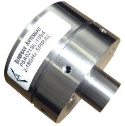
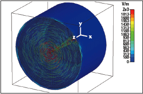
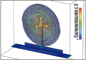
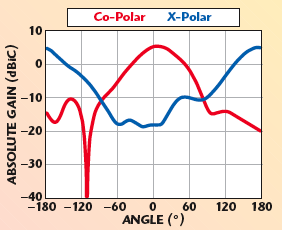
The spiral antenna has long been used in military applications for direction finding systems and for general threat detection. Figure 1 shows a typical 2 to 18 GHz, cavity-backed spiral antenna and Figure 2 shows an electromagnetic simulation performed on such an antenna, indicating the field strengths present on various parts of the structure. In these applications, the antennas generally have requirements for a uniform pattern shape, with respect to amplitude and phase from one antenna to another. Also, the main beam should exhibit a smooth curve without any points of inflection, which is said to be monotonic. A typical radiation pattern for such an antenna is shown in Figure 3. It is generally more important in these applications to control the beam shape and match the performance of the antenna from unit to unit than to maximise the gain of the antenna. For many commercial communication systems, it is more important to fill efficiently an area with a signal than to produce a very precise beam shape. The spiral radiating structure used in this example is very much suited to this mode of operation, but no longer needs to be used in conjunction with a cavity loaded with an absorber. Two types of antenna can then be created using this type of structure: a bi-directional structure where the spiral is allowed to radiate freely into space in both directions normal to its plane, or a higher gain, uni-directional structure, where a reflector plate is positioned close to the spiral such that the radiation in one direction is reflected and the forward gain is therefore enhanced. Figure 4 shows a bi-directional spiral antenna. Note the additional proprietary features used to extend the frequency coverage. An electromagnetic simulation of a similar type of antenna is shown in Figure 5. The radiation characteristics for a bi-directional spiral antenna such as this are shown in Figure 6. It can be seen that when the polarisation is left-hand circular in a forward direction, it is right-hand circular in the opposite direction. Thus, in a transition region in between, it will be linear. Such a pattern is an advantage in many deployments. For example, if an antenna is to be placed in a corridor or hall, then a bi-directional antenna of this type is ideally suited. Sometimes, a more directional antenna is desired while retaining its broadband properties. This would typically be for a deployment in the corner of the area to be covered, such as a large hall or atrium. In this case, the reflector plate serves to increase the gain in the forward direction. Figure 7 shows a typical radiation pattern for such a uni-directional low profile spiral antenna. Depending upon the size of spiral selected, it is possible to provide coverage across the band between 400 MHz and 6 GHz. These antennas are used in systems where all the communication bands are required to be transmitted or received by a single antenna, either when originally installed or at some time in the future.

Bi-conical Antennas
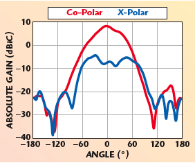
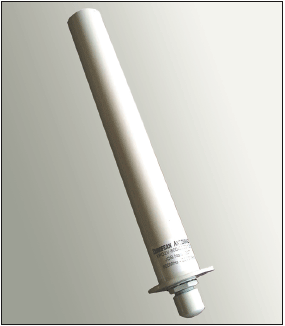
Bi-conical antennas can be designed to operate effectively over a large frequency range. These antennas produce a linearly polarised signal and exhibit extremely low azimuth ripple, meaning that the omni-directional characteristics are excellent. Depending upon the degree of input return loss degradation that can be tolerated, the effective bandwidth of such a structure is in the region of two octaves. This will depend upon the extent to which the structure has been miniaturised by the choice of transition region from a cone to a cylinder, or if an entirely conical section has been used. Figure 8 and 9 show a bi-conical antenna and its electromagnetic simulated results, respectively. Figure 10 shows its measured performance and the very low ripple in the azimuth pattern can clearly be seen. Although the high power handling capability is not always important in commercial communications systems, the small size of these structures makes them very attractive in this application. For example, a product capable of covering the whole frequency band from 800 MHz to 2.2 GHz can be packaged in a structure of 32 mm diameter by 225 mm long. It is possible to achieve wider bandwidths, but a compromise has to be made in terms of the diameter of the product. A larger diameter could extend the frequency of operation. These antenna structures retain their radiation pattern characteristic over this very wide frequency range. This makes them suitable for microcell and picocell applications where the antennas can be employed to provide a signal boost (in a railway station, for example). Antennas with this kind of radiation pattern would be the most effective for a central deployment.
Conclusion
There is an increasing demand for new frequency bands to be added to modern communications networks. As these new frequency bands become available for commercial use, system antennas have to be upgraded to cover these additional frequencies. If an existing antenna was not originally designed with sufficient bandwidth, it will not maintain its performance over these wider frequency ranges. However, design variations, applied to traditional spiral and bi-conical broadband antenna structures, have resulted in commercial products that are well suited to these requirements, using technology originally developed for military applications.
Chris Walker received his BSc degree in theoretical physics from Cambridge University in 1982. He has worked with EEV, Litton and CPI, developing vacuum tubes for radar and communication systems. He joined European Antennas, part of Cobham Antennas Division of Cobham plc, in 1998, where he has been involved in the design and manufacture of directional flat panel antennas, base station sector antennas and omni-directional antennas within the range from 250 MHz to 40 GHz for military and commercial applications within satellite, data, WiMAX, WLAN, telemetry, security, surveillance and broadcast systems. He is presently technical director of European Antennas Ltd. with responsibility for assessment, modeling and development of antennas for future technologies.


Chris Walker