
How do you design, develop, and produce an airborne blade antenna to cover 30 to 2000 MHz and achieve greatly improved performance, especially at the low end of the band for SINCGARS applications, while maintaining its small size for mounting on sub-sonic aircraft and helicopters? Astron has had a series of R&D/Production program over the last nine years achieving miniaturized antennas for communications and Direction Finding (DF) Arrays for the U.K., US Army/Navy, Australia, and others for submarines, ships, UUV/UAV, aircraft and Land Mobile systems.
The resulting Astron antenna and Direction Finding Array technology has over years, evolved into Astron’s “HESA™ TECHNOLOGY”. This unique and proprietary set of advanced techniques provides for High Efficiency, Sensitivity, and Accuracy in all our miniaturized and standard DF antenna systems. A major benefit of the HESA™ Platform includes the ability to co-locate multiple antennas and their associated electronics in a small package; oftentimes exceeding but always maintaining performance parameters equal to their larger counterparts.
The HESA technology applied to the miniaturized JTRS/SINCGARS Blade antenna, stresses:
-
Size
To operate at the lower frequencies (antenna height is much less than λ4) we can expect lower gains. As an example, at 30 Mhz λ4 is 8.3 ft. We are allowed about 18" for the airborne blade height. The antenna being much shorter than λ4 at 30 Mhz will have its VSWR suffer and the required broadband matching networks will present attenuation and a decreasing gain.

It is obvious that, certainly at the lower frequencies, in order to increase the antenna gain, it is essential that the antenna be miniaturized. It was, therefore, important to examine the fundamental limits and parameter trade-offs involved in antenna size reduction. First we need to evaluate the size versus operating frequencies and bandwidths of conventional antennas. This analysis is based on the work of the Astron and Virginia Polytechnic Institute (Professor Warren Stutzman) team performed on a recent DAPRA antenna miniaturization program.
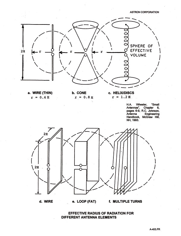
The size of the antenna is measured by the radius, r, of a sphere that just encloses the electrical radiating area of the antenna and its ground plane mirror image (H.A. Wheeler, ASmall Antennas@, Chapter 6, pgs 6-9; R.C. Johnson, AAntenna Engineering Handbook@, McGraw Hill, 1993). This size should be measured as an electrical size, which is the principal size relative to a free space wavelength, λ, see Figure 1.

The radiation characteristics of electrically small antennas (r#0.16λ) was first investigated by H.A. Wheeler, AFundamental Limitations of Small Antennas@, IEEE, Vol. 69, pg 1479-1484, Dec 1947. One year later, L.J. Chu, APhysical Limitations of Omni-Directional Antennas@, J. Appl. Phys., Vol. 19, pg 1163-1175, Dec 1948, derived an approximate expression for the minimum radiation Q of a small antenna. In 1960, R.F. Harrington, AEffects of Antenna Size on Gain, Bandwidth, and Efficiency@, J. Res. Nat. Bureau of Standards, Vol. 64-D, pg 1-12, Jan/Feb 1960, extended Chu=s theory to include circularly polarized antennas. Shortly thereafter, R.E. Collin and S. Rothchild, AEvaluation of Antenna Q@, IEEE TAP Vol. 12, pg 23-27, Jan 1964, and R.L. Fante, AQuality Factor of General Ideal Antennas@, IEEE TAP Vol. 17, pg 151-155, Mar 1969, derived exact expressions for the radiation Q based on evanescent energy stored around an antenna.
To provide closure on the history of these important concepts, it is to the credit of R.C. Hansen, AFundamental Limitations in Antennas@, IEEE, Vol. 69, pg 170-182, Feb 1981; that he assembled, integrated, and promulgated much of this information. These corrected and refined relationships are plotted in Figure 2.
The efficiency family of curves includes the dependence of antenna radiation efficiency, η. The top curve is for 100% radiation efficiency. It shows that for a small electrical antenna, say for Kr<1, Q increases dramatically as size is reduced.
To utilize the curves of Figure 2., a point is located for the antenna Q (center frequency of the operational bandwidth) and the antenna=s value of Kr at the center frequency of operation. The enclosed radius, r, of the antenna is based on the antenna configuration=s effective aperture area (see Figure 1) and includes any image of the antenna in the ground plane.
Astron has been using these curves in many of its R&D programs for DoD and found them an excellent guide in determining the potential gain, bandwidth, Q, efficiency, etc. for advanced designs and recognition of the point during antenna developments at which further efforts will not provide any significant improvements in bandwidth and efficiencies unless dielectric and/or ferrite loading is used. The use of this type of loading is the only way to defeat Chu-Harrington Criteria.
-
ANTENNA MINIATURIZATION - Dielectric/Ferrite Loading
To illustrate the use of this powerful dielectric/ferrite antenna loading tool, let us apply it to the external dielectric/ferrite loading of a monopole, see Figure 3. A test was run, on the Astron VHF/UHF calibrated range to verify the theory regarding the ideal location of dielectrics and ferrites on a monopole antenna to achieve maximum foreshortening. A special jig composed of a hollow 20 inch low RF loss fiberglass cylinder (1 inch O.D.) was devised for holding a 20 inch, 1/8 inch O.D. copper rod at the tube=s center in a vertical position. The first test, 89A, involves getting the copper rod (operating as a monopole) RF response versus frequency with the HP network analyzer set to sweep over the frequency range of 20 to 160 MHz. The 20 inch rod monopole has a maximum response at its resonance frequency of 135 MHz, see Figure 3. Its efficiency at its resonance frequency should be 100%, and indeed it is, note the 100% efficiency mark at the 132 MHz mark obtained from the range initial calibration.
The next test, 89C, involved filling the lower 5 inch of the fiberglass cylinder jig (still holding the 20 inch rod at its center axis in a vertical position) with a powdered ferrite having a μ of 4. The powder surrounded the rod at its base, externally loading the bottom 5 inches. The maximum foreshortening expected would be the square root of 4 or 2:1. The 1/8" copper rod is only partially loaded with ferrite material. The effect of the ferrite was to lower the resonance frequency to 112 MHz (from 135 MHz). This effectively achieved only a foreshortening of 1.24, the 20 inch rod=s electrical length effectively being increased from 20 inches to 24.8 inches.
The next test, 89H, removed the ferrite powder and added 5 inches of dielectric powder (ε = 4) at the top 5 inches of the rod. The result was similar to test 89C, a decrease of the resonance to 112 MHz and an effective foreshortening of 1.24.
The last test, 89P, left the 5 inches of dielectric at the top 5 inches, and returned the 5 inches of ferrite powder at the bottom of the 1/8" rod. The resonance dropped to 98 MHz, a foreshortening of about 1.5, and increasing its effective electrical length to 28 inches. In all tests the efficiency was essentially 100%.
These tests showed that the optimum position for the ferrite is at the base (where the current is the highest) while the optimum position for the dielectric is at the top (where the voltage is highest).
-
Gain/Bandwidth
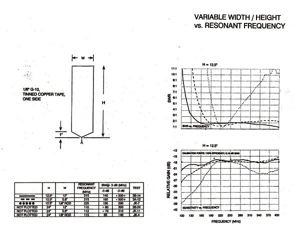
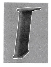
Data for a constant height antenna (12.5”) while varying its width incrementally, 12”, 5.8”, and 1/8”, clearly shows the expanding gain/bandwidth, see Figure 4. It was the combining of the above discussed HESA™ Technologies which enabled Astron to achieve the desired JTRS/SINCGARS airborne blade antennas, see Figure 5. Other HESA™ Technologies are available for Direction Finding Arrays, SATCOM and UHF/VHF/UHF communications antennas.
About the Author
Joseph R. Jahoda, Astron’s Chief Technology Officer, founded Astron 27 years ago. He graduated from College of the City of New York in 1950 with a B.E.E., and from Polytechnic Institute of Brooklyn in 1954 with a M.E.E. He has been involved in R&D for ECM and Communications System ever since.