
Setting new standards in flexibility and performance and opening the possibility for new applications, the R&S SMU200A is said to be the first high end generator to combine two complete digital signal generators with modulation capabilities in one instrument. It provides space for up to two RF paths in an instrument that occupies four units of rack height. For the first RF path, the user can choose from four different frequency options (upper frequency limit 2.2, 3, 4 or 6 GHz). In addition, a second RF path with up to 2.2 or 3 GHz can be installed. The lower frequency limit is 100 kHz for all options. Both RF paths have I/Q modulation capability via the internal baseband section of the instrument, while the first RF path can also be modulated with external analog I/Q signals. Furthermore, the baseband section is completely digital and can accommodate up to two I/Q baseband generators.
New Applications
Having two signal generators in one obviously offers a space saving of 50 percent but the two-path concept also means that applications can be accommodated that previously would only have been possible by using a number of signal generators at high cost and with great effort. The advantage is that if two baseband generators are built in, their output signals can be digitally added and fed to the I/Q modulator of an RF path, if necessary weighted and with an application-specific frequency offset. One baseband generator can also trigger the other, which allows a defined time offset between the signals. Thus, it is possible to create complex scenarios with a maximum bandwidth of 80 MHz using only one RF path - for example, the simulation of the multicarrier signal of a 3GPP base station for receiver tests on mobile stations. In this case, baseband generator A provides, in real time, the desired signal to be demodulated by the receiver. Baseband generator B produces a matching multicarrier signal as the background signal using its arbitrary waveform generator.
Another possible application is 3GPP transmit diversity, in which a base station transmits differently coded signals via two antennas. For example, an R&S SMU200A with two baseband generators can simulate this to test the receiver of a mobile phone. For this scenario, baseband generator A produces the signal of antenna 1 and baseband generator B that of antenna 2 (each in real time with channel coding). As both signals are transmitted on the same RF frequency, only one RF path is necessary.
With two RF and two baseband paths, the two-path vector signal generator can also generate signal combinations having large differences in power and frequency offset, including the desired signal and the modulated interfering signal in receiver tests, for example. Now modulation signals up to 80 MHz wide are possible in each path.

An Intuitive Operating Concept
To optimally support users specifically for these complex scenarios, a modern operating concept with a graphical user interface has been developed. The most important element is the block diagram (see Figure 1 ), which shows the complete signal flow from the baseband to the RF output. Each block represents a functional unit of the instrument and the block diagram allows users to see at all times which blocks are active and at which point in the signal flow a particular parameter takes effect. Active control signals, such as triggers or markers, are also displayed in the block diagram, while submenus are displayed by means of windows. Operation of the instrument is possible via the front panel as well as with a keyboard and mouse.
The graphics block can show the generated baseband signal in all conventional display modes - I(t), Q(t), vector diagram, constellation diagram, frequency spectrum, etc. The display is in real time with the aid of a built-in transient recorder, which makes it easy to check whether the signal is being generated as desired. Also, the context-sensitive help system provides users with further support. It contains the entire operating manual and features numerous navigation possibilities, including full-text search.
Universal Coder
The core of an R&S SMU200A baseband generator is a universal coder with digital signal processing (DSP) and a coprocessor field programmable gate array (FPGA) for calculating complex signals in real time. Thus, it is able to generate signals for all conventional mobile radio standards. The universal coder features ASK, FSK (including MSK), PSK (including 8PSK EDGE) and QAM (up to 1024QAM) as modulation modes, plus all generally used baseband filters and coding types. PBRS sequences, patterns, data lists and external data are available as data sources via different interfaces (serial, parallel, USB).
In addition, each baseband generator contains an arbitrary waveform generator (ARB) with a 56 Msample memory for I and Q and four marker bits per sample (256 Mbyte). Due to the built-in hardware interpolation filter, low over sampling values can be used, which increases the effective memory. The new instrument is also supported by WinIQSIM™ simulation software and, therefore, all standards that can be generated by it, including WLAN 802.11 (a, b and g), cdma2000 and 3GPP TDD low rate (TD-SCDMA) and high rate.
Furthermore, the instrument features software options tailored to important mobile radio standards. Initially, the instrument comes with the 3GPP FDD and GSM/EDGE options. There is also an option for generating continuous wave (CW) multicarrier signals, as they are frequently needed in amplifier tests.
When the GSM/EDGE option is used, the new two-path vector signal generator can change the modulation between GMSK and 8PSK EDGE in real time and offers all burst types defined in the standard. Furthermore, in the new-framed (double) mode, multiframe scenarios can be created, such as an idle burst every 26 frames, or a modulation change over time in a specific time slot.

The real time capabilities and the ARB of a baseband generator are combined in the digital standard 3GPP (see Figure 2 ). In downlink mode, up to four code channels (PCCPCH and up to three DPCHs), including channel coding, can be generated in real time. Altogether the signal generator can simulate as many as four base stations with 128 DPCHs each (plus control channels). Thus, all conceivable scenarios can be implemented, ranging from the standard-compliant reference measurement channel - optionally with orthogonal channel noise simulation (OCNS) - to simulation of a base station under full load. In uplink mode, up to 67 mobile stations are possible. In this case, mobile station 1 can simulate the three modes PRACH, PCPCH and DPCCH+DPDCH in real time and with channel coding. Receiver tests on 3GPP base stations according to TS 25.141 can thus be performed.
The I/Q signals generated in this manner can be provided with additive white Gaussian noise (AWGN) or artificial I/Q distortions, if necessary. Modern 16-bit DACs are used for the final digital-analog conversion.
High Signal Quality
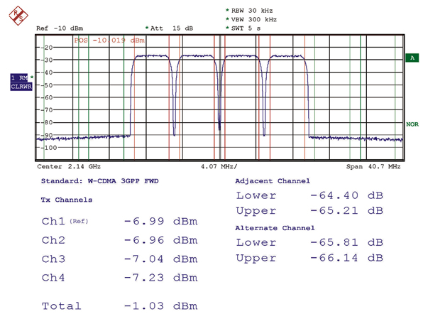
A decisive criterion for rating a signal generator is the quality of the generated RF signals. Here, too, the SMU200A has advantages. Its single sideband (SSB) phase noise is typically -135 dBc at 1 GHz (20 kHz offset, 1 Hz measurement bandwidth). With a 3GPP test model 1, 64 DPCHs, the instrument attains ACLR values of typically 70 dB in the adjacent channel and typically 74 dB in the alternate channel. With a 3GPP four-carrier signal like the one shown in Figure 3 , the SMU200A reaches typically 64 dB in the adjacent channel and typically 65 dB in the alternate channel. At the same time, the vector error of the generated signals is very small (for 3GPP typically 0.3 percent with 1 DPCH, rms).
Also, the I/Q modulator has an RF modulation bandwidth of 200 MHz, which can be fully utilized in path A with external analog I/Q signals. If the internal baseband section is used, an RF modulation bandwidth of 80 MHz (per installed path) is available, making the two-path vector signal generator ideally prepared for broadband systems of the future. A new type of digital ALC ensures high level linearity and repeatability of typically 0.05 dB for modulated signals and the level of accuracy better than 0.5 dB.
An electronic attenuator ensures wear-and-tear-free switching over the entire level range and the standard model features up to +13 dBm (PEP). With the high power output option, the output power can be increased to +19 dBm (+26 dBm in overrange). The high power output option is installed alongside the electronic attenuator, so the latter can continue to be used in the normal level range.
Conclusion
By combining two complete digital signal generators with modulation capabilities in one instrument the R&S SMU200A provides a diverse and flexible capability that enables users to take a new approach to testing and opens up new applications that previously would not have been possible without considerable cost and effort. Additional information may be obtained via e-mail at customersupport @rsd.rohde-schwarz.com.
Rohde & Schwarz GmbH & Co. KG, Munich, Germany, Tel: +49 89 4129-13779, Fax: +49 89 4129-13777, www.rohde-schwarz.com. Circle No. 307