
 ASK HARLAN
YOUR RF & MICROWAVE TECH Q&A RESOURCE
You may know Harlan Howe from his twelve years as publisher and editor of Microwave Journal ®, or from his 34 years as a Microwave design engineer and engineering manager, or from his service as an IEEE fellow and past president of MTT-S.
Now, although semi-retired, Harlan is available to answer your questions about RF and Microwave engineering. If he doesn't have the answer, he will find an industry expert who does.
Click here to submit your question now.
FROM: Jerry Anderson
Harlan Howe
Hi I would like to know what the [attached] circuit diagram does?
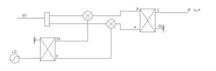
1) Is this a SSB suppression technique?
2) If not what dose it do if the combiner hybrid is 90 or 180 degrees?
Thanks for you input on this
Jerry Anderson
--------------
Dear Jerry,
Yes, the circuit is a SSB (single sideband) mixer. In order to function, either the input hybrid or the LO hybrid must be 90 degrees. The other splitter needs to be in phase. However, the choice of which one goes where is optional.
FROM: Dan Schwartz, Micro Systems Inc.
In using chip capacitors on microstrip circuitry, is there an optimum capacitance reactance for say a 50 ohm trace? Or does one choose the greatest capacitance without having resonances within the operating frequency range? I can't find a rule-of-thumb for selecting coupling capacitors for microstrip circuitry.
--------------
Dear Dan,
The value of the capacitor as a DC block will be a function of the frequency of operation of the circuit. In general a reactance of less than 1 Ohm for a 50 Ohm line at that frequency is adequate for most applications.
FROM: Albert Lin, Excelics Semiconductor
What is push-pull oscillation?
--------------
Dear Albert,
A push-pull oscillator is a balanced circuit that uses complementary devices 180 degrees out of phase to improve the noise characteristics. A discussion and schematic can be found in: RF Design Guide, Peter Vizmuller, Artech House, 1995, pp 140-141, ISBN# 0-89006-754-6
FROM: Zephyr Hay, DataLine
The Delay Line detectors are most widely employed in Digital receivers for modulations like PCM/FM. Links about the theory of this decetor, its importance and the factors for selecting its delay element are required.
--------------
Dear Greg,
This is not one of my areas of strength. However, according to the Communications Standard Dictionary by Martin H. Weik, Chapman and Hall, 1996: trellis coded modulation (TCM) is,"Modulation that (a) is a modification of continuous phase modulation (CPM), (b)improves performance without changing bandwidth, (c) when filtered, does not have the constant envelope of CPM, and (d) uses expanded signal sets that make it useful in the design of spectrally efficient communications systems." There is a discussion of TCM on PP183-184 of Digital Communications, A. Bateman, Addison-Wesley, 1999, ISBN 0-201-34301-0
It is also related to Viterbi decoding, which is discussed in chapter 8 of Error-Control Coding and Applications, Djimitri Wiggert, Artech House, 1978, ISBN 0-89006-066-5.
FROM: Emily Hou, Chengdu A-INFO Science & Technology Inc.
We are a China based RF and Microwave Company. We are looking for a supplier for gold-plate service. Do you happen to know companies who can provide this service? Your suggestion and help is highly appreciated! Thanks a lot in advance!
--------------
Dear Emily,
We do not have any plating shops in our buyer's guide. There are usually several shops that do precious metal plating in the Yellow Pages telephone directory for any major US city. I don't usually suggest specific companies, however, since you don't have access to our telephone directories, I picked out several local Boston shops that have web addresses:
Cambridge Plating Company www.nmfrc.org/cambridge
F.M. Callahan and Son, Inc. www.callahanplating.com
P&L Electroplating Co. www.thomasregional.com/ene/p&l
I hope this helps.
Harlan Howe Editor
FROM: Rene Poirier, Telus Quebec
In the context of FWA - Fixed Wireless Access, and 802.16a which covers all frequency bands from 2 to 11 GHz: Do you have references or estimation of the first-wall penetration loss as a function of frequency (2-11 GHz) that an indoor CPE would experiment with its base station?
--------------
Dear Rene,
Propagation loss through walls is a function of frequency, materials, thickness and methods of construction (wooden studs vs. metal studs, etc). While many of the wireless LAN texts discuss propagation losses in generalities, I have not found any published data for specific types of walls. When I had a similar problem, as an engineer many years ago, we made measurements. That may still be the best solution.
FROM: Kanti Patel, Lockheed Martin
Can you let me know which are the modes that need to be taken into account when you design a circular waveguide (te11 mode CP propagation) and rectangular waveguide (te10 mode single mode)choke flanges. For example, if you need a short circuit 90 deg stub choke design, the length of the short circuit stub (slot) is typically quarter wavelength for which mode?
--------------
Dear Kanti,
The chokes should be a quarter of the guide wavelength for the dominant mode. The guide wavelength is a function of the cutoff wavelength for the given waveguide dimensions. Data on the cutoff wavelength and the equations for guide wavelength can be found in: Microwave Engineer's Handbook-Vol.1, T. Saad, 1971, which is still available from Artech House.
FROM: Kausn Chandrasekara, student
Dear Harlan,
I am an RF engineer from Suntel,Colombo. Recently we were introduced with a WLL product in the range of 2 ~ 3 GHz Range. To my surprise they said their modulation is sort of a spherical modulation method which can turn around buildings and trees. But when I asked "Are you talking about spherical polarisation and diffraction ?" they said NO NO ! It just turnes around objects. Mr.Harlan do you have the slightest idea of this kind of a funny modulation method ? Looking forward to hear from you soon.
Thank you for your usual assistance. Best Regards, Kasun.
--------------
Dear Kausn,
If they can't explain the mechanism, it's probably the imagination of the sales department. I don't know of any way to make a microwave signal turn corners by itself, except by reflection.
Propagation loss through walls is a function of frequency, materials, thickness and methods of construction (wooden studs vs. metal studs, etc). While many of the wireless LAN texts discuss propagation losses in generalities, I have not found any published data for specific types of walls. When I had a similar problem, as an engineer many years ago, we made measurements. That may still be the best solution.
FROM: Deepak Ghodgaonkar, MARA University of Technology
I am looking for manufacturers which make 1 kHz modulators for WR-90 X-band waveguide. I would like to use it with Slotted Line.
Thank You, Deepak
--------------
Dear Deepak,
Most of the major test equipment manufacturers provide waveguide test accessories. I suggest that you check the test equipment category at our online buyer's guide.
FROM: Duncan Simpson, simpco. maint.
Looking for successful ways to shield against electromagnetic pulsed energy.
--------------
Dear Duncan,
Check out the shielding and absorbing categories in our online buyer's guide. The choice of techniques is a function of the frequency, power levels, isolation needed, size, weight and the environment.