
Enhanced performance is needed from antennas, radomes and other microwave components to support ever-increasing functionality for military communications and electronic warfare (EW) applications. There is a continuing demand for antennas with broader bandwidth, higher power handling and better controlled radiation patterns, while at the same time reducing size and weight. Nurad Technologies is working to satisfy these difficult and sometimes conflicting requirements by developing broadband antennas and mating radomes that produce two orthogonal simultaneous polarizations.
Quad-ridged Horn Antennas
Rectangular waveguide has long been the transmission line of choice for high power microwave applications. Its attributes include very high power handling capability, extremely low insertion loss, single mode (TE10) operation over a 1.5:1 bandwidth and mechanical ruggedness suitable to a broad range of environmental conditions. For applications requiring broader operating bandwidth ridges are incorporated into the waveguide broad walls to form dual-ridged waveguide. Figure 1 shows a cross section of a typical dual-ridged waveguide which can support single mode operation over bandwidths up to and beyond 3.5:1. This enhanced bandwidth can be understood by considering the center ridged section as a parallel-plate transmission line, thereby lowering the waveguide cut-off frequency to below that of conventional waveguide.

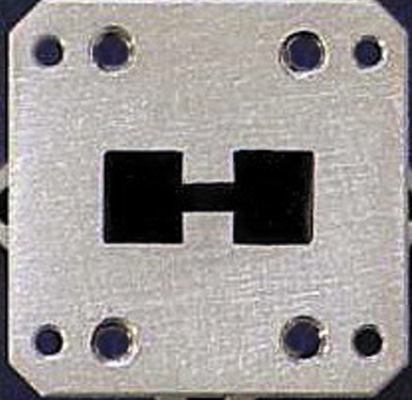
Ridges can be employed in waveguides of various cross sections including the more general circular and square cases. Figure 2 shows a typical square waveguide that supports two orthogonal modes and hence incorporates four ridges, one on each wall. This quad-ridged configuration is used in applications where either dual-linear polarization or circular polarization is desired in horn antennas.
These horn antennas can be thought of as transformers that match the impedance of the quad-ridged waveguide modes to that of free space. Ridges are designed for optimum impedance match over a broad bandwidth while also handling high microwave power. A key issue in achieving such performance is properly designed transformer sections (ridge height, ridge width, waveguide dimensions), and careful attention to narrow conductor gaps and sharp edges to avoid electromagnetic breakdown. In addition, well designed antennas must maximize internal symmetry for high port-to-port isolation and polarization purity, and use precision manufacturing techniques such as electrical discharge machining (EDM).
Horn antenna gain and radiation pattern shape is controlled by ridge geometry, aperture size and shape, and external lenses. For many applications very specific gain, and azimuth and elevation beamwidths are desired across the entire operating bandwidth, and external dielectric lenses are key to realizing this performance. These lenses are precision-machined dielectric material of dielectric constant ranging from 1.5 to 6. The lenses are installed within the horn aperture and shaped such that the desired frequency independent performance is achieved.
|
Table 1 | |
|
Frequency range (GHz) |
6 to 18 |
|
SWR |
2.5 max |
|
Gain (dBi) |
10 nominal |
|
Beamwidth |
60° nominal |
|
Polarization |
Dual slant linear |
|
Port-to-port isolation (dB) |
-25 min |
|
RF power (W) |
200 CW (100 per port) |
|
Environmental |
Aircraft |
Model 120DL4 Horn Antenna
Table 1 provides representative requirements for an example of a high power broadband dual-polarized antenna that operates over a 3:1 bandwidth. The model 120DL4 is an example of one such antenna. This high performance horn antenna is dual linearly polarized and operates over the 6 to 18 GHz frequency range with an SWR of less than 2.5:1. It provides high radiation efficiency over the entire 3:1 bandwidth with a nominal beamwidth of between 45° and 90°. The unique design of model 120DL4 allows dielectric lenses to be added for custom beamwidths and shaped radiation patterns. Key features of the model 120DL4 antenna also include excellent RF power handling up to 200 W CW (100 W per port), high port-to-port isolation and a convenient compact size. The superior design of this antenna makes it suitable for use in the extreme environment of high dynamic airborne flight. A protective radome can easily be integrated with the horn antenna to form a complete airborne antenna system.
Radiation Patterns
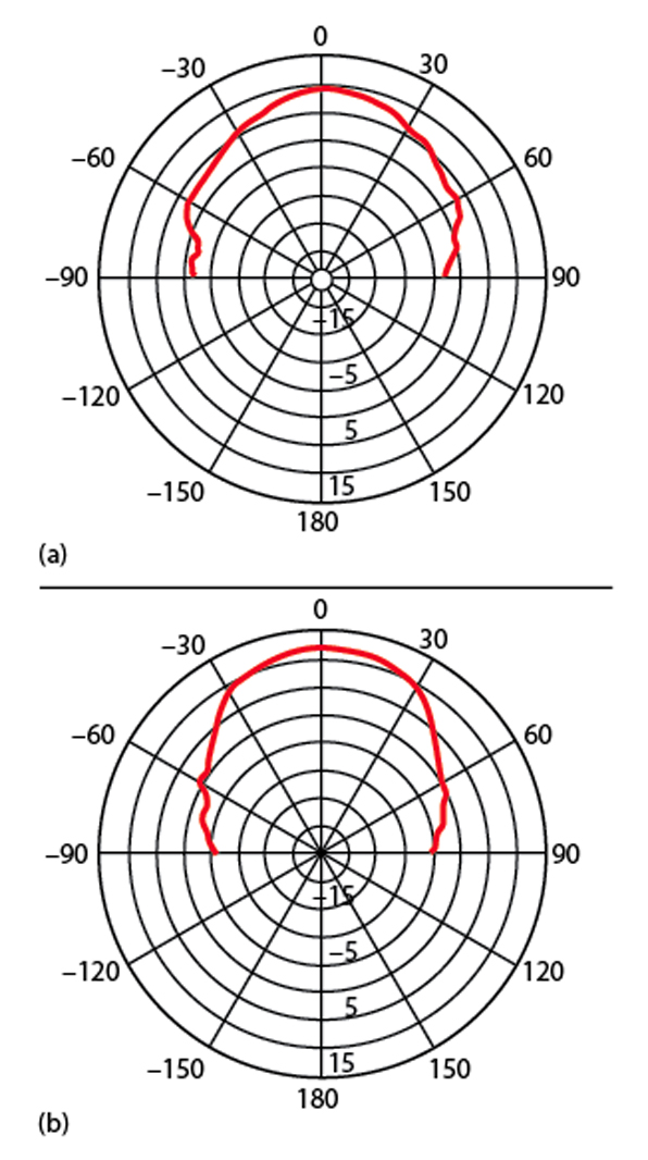
Typical radiation patterns of the 120DL4 horn antenna are as shown in Figure 3 . These polar plots at 6 and 18 GHz exhibit the desired symmetric radiation characteristic required for polarization diverse applications. The plots are the response measured from one of the two antenna ports with a linearly polarized source antenna. The antenna provides coverage over a fairly wide angular region, and peak gain increases with frequency from 8 dB at 6 GHz to 12 dB at 18 GHz. As previously discussed, lenses can be incorporated into the aperture of this antenna to produce custom coverage and gain performance for specific applications.
Conclusion
A series of high performance antennas has been designed for EW and communication applications. The new model 120DL4 dual linearly polarized antenna operates over the 6 to 18 GHz frequency range, providing high radiation efficiency over the entire 3:1 bandwidth. It is suitable for use in the extreme environment of high dynamic airborne flight, for which a protective radome can be included for a complete airborne antenna system. In addition, it is an ideal antenna for applications requiring polarization diversity.
Nurad Technologies Inc., Baltimore, MD (410) 542-1700, www.nurad.com. Circle No. 303