
Broadband synthesizers based on direct digital synthesis (DDS) technology have traditionally led the industry in frequency agility and switching performance, but have also led in high NRE and recurring costs. These high costs stem from the custom nature of DDS-based synthesizers and have resulted in digital synthesizers being primarily utilized in those military applications where the tradeoff favors performance over cost.
Manufacturers of DDS-based synthesizers have long recognized this drawback of their products, which has led to the introduction of various modular architectures to reduce the level of customization required. Though these architectures were undoubtedly an improvement and a step in the right direction, they still did not solve the fundamental cost disadvantage of DDS-based synthesizers relative to their analog counterparts.

The WaveCor™ synthesizer is the next step in DDS-based synthesizer evolution and is designed to eliminate this disadvantage and provide maximal user value. WaveCor is realized by leveraging ITT's patented low spurious direct digital synthesis technology. This advanced DDS technology provides spurious free dynamic range of greater than -80 dBc combined with low phase noise, precise frequency control and ultra-fast switching.
The key advantage of utilizing this DDS technology for synthesizer design is that the purity of the baseband signal enables a radical simplification of the product's architecture. The WaveCor synthesizer utilizes a very simple, flexible architecture that provides a precisely tailored solution meeting the user's performance and cost targets.
WaveCor's Software-based DDS Technology
WaveCor's patented DDS technology does not use memory-based techniques, but rather is computationally or software-based, offering much greater performance over older memory-based approaches. Some highlights of the benefits of this DDS technology include picohertz tuning resolution, spurious free dynamic range (better than -80 dBc), low phase noise (better than -145 dBc/Hz at 1 kHz), ultra-fast switching (less than 200 ns) and low power consumption (5 W average).
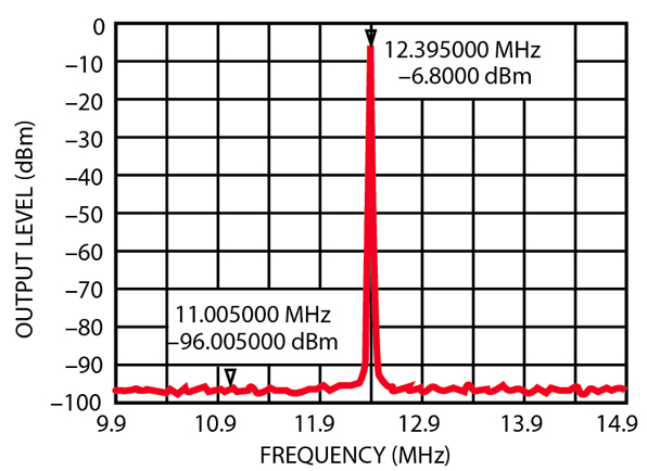
As illustrated by the performance highlights of this DDS technology, the standard tradeoff of phase noise versus spurious free dynamic range present in prior digital synthesis techniques is eliminated. With a computational DDS, spurious content can be reduced while simultaneously reshaping and optimizing phase noise. Figures 1 and 2 display the WaveCor synthesizer's typical phase noise and spurious free dynamic range, respectively.
An ancillary, but very important benefit derived from the use of a software-based DDS, is the enhanced modulation and waveform control that is realized. Besides the traditional FM or "chirp" capability provided by most DDS products, the WaveCor's DDS provides a multitude of additional waveform functionality. To augment traditional FM, piecewise nonlinear FM is supported. Various FM segments can be chained together to produce complex arbitrary waveforms.
For radar applications, a built-in doppler pulse controller is available. This controller provides precise control of the pulse's start, pulse width, off time and number of repetitions. For communication applications, the DDS supports true digital I/Q modulation capability. Numerical techniques can produce modulated waveforms with signal-to-noise ratios in excess of 50 dB.
Though this exceptional performance is impressive, the key advantage of this DDS technology is the advance in synthesizer architecture simplification that is now achievable. It is no longer necessary to utilize complex, expensive custom circuitry to compensate for the shortcomings of the DDS-generated baseband signal.
Flexible Architecture
The ability of the WaveCor synthesizer to utilize the output of the DDS "as is" eliminates the need for extensive mix/divide circuitry. Typically, such circuitry is required to compensate for the high spurious content of commercially available DDS products. This additional circuitry is highly customized for a specific application with customization resulting in significant engineering effort and long lead times for new synthesizer applications.
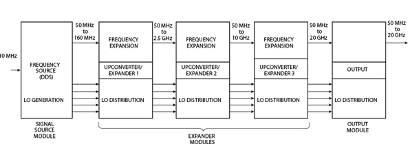
The elimination of this "cleanup" circuitry led to the highly flexible WaveCor synthesizer architecture. With WaveCor's DDS technology and a carefully engineered frequency plan, modules can be removed and replaced in a "plug-and-play" manner. This flexibility allows the synthesizer's architecture to meet multiple output frequency/bandwidth requirements. The top-level block diagram of the 20 GHz WaveCor synthesizer is shown in Figure 3 . As shown, there are three different module types - a signal source module, expander module(s) and an output module. Any WaveCor synthesizer will have exactly one signal source module and one output module, but may have a variable number of expander modules, based on the desired output frequency and/or bandwidth.
The unique aspect of the WaveCor architecture is that each expander module is available in one of three different classes, each offering a different level of performance. These three classes are multiplication, direct conversion and mix/divide.
The easiest way to view these three classes is in terms of the effect that each has on the purity of the signal provided by the signal source module. The mix/divide modules will enhance the purity of the WaveCor generated baseband signal and the direct conversion modules will maintain the signal's purity, while the multiplication modules will tradeoff degradation of the baseband signal for significantly reduced cost.
It is important to note that even though the modules are designed to meet different performance levels for each class, modules from each class are completely interchangeable. Synthesizer designs can combine modules of different types and specification levels to quickly and efficiently meet the user's requirements.
Signal Source Module
The first module in the WaveCor synthesizer is the signal source module. This module provides the primary interface with the external system, including DC power, programming/control, modulation and a master reference input and output.
The signal source module produces all of the RF signals needed by the remainder of the synthesizer. These RF signals include the primary output and a series of five local oscillator (LO) signals.
The primary RF output of the signal source module is the output that is externally controlled. It typically provides fast, fine frequency steps, as well as linear FM (chirp) and nonlinear FM (NLFM) modulation capability.
The LO signals are continuous wave (CW) signals, which are used by the expander modules. These five signals are internally generated by the signal source module and are passed from module to module. The frequency and amplitude of these signals are fixed and cannot be changed.
The signal source module includes the digital interface. Both a generic serial (LVDS) and parallel (TTL) interface is implemented. The interface controller is reprogrammable, so custom interface requirements can be easily met.
The analog interface circuitry also resides in the signal source module. The primary function of the analog interface is to connect an external system reference to the internal, high performance WaveCor reference. The standard reference input is 10 or 100 MHz, but reference inputs between 5 and 100 MHz can be supported by simply reprogramming the input PLL.
Expander Modules
The expander modules are used to increase both the center frequency and useable bandwidth of the signal source module. Depending on the desired output frequency, one, two or three expander modules may be used. Each module may be of any performance class.
Expander 1 is the first expander module. This module increases the signal source output to cover a bandwidth of 50 MHz to 2.5 GHz. The output of this module can connect directly to either the next expander module or to an output module resulting in an S-band synthesizer.
The next expander is Expander 2. This module utilizes the S-band output of the previous expander as its input to produce an output of 50 MHz to 10 GHz. This expander produces output frequencies above 2.5 GHz, while the output of the previous expander is passed through.
Expander 3 is the final expander module. It receives the 10 GHz bandwidth of Expander 2 and produces an output covering a bandwidth of 50 MHz to 20 GHz. As is the case with the previous expander, Expander 3 produces the output above 10 GHz and passes through the output of Expander 2 for frequencies below 10 GHz.
Note that each expander module has a primary input and output, as well as LO inputs and outputs. The primary signals are the (modulated or stepped) RF synthesizer output, while the LO signals are CW signals used by the direct expanders. This standard interface also allows for rapid customization of expander slices to accommodate custom frequency outputs such as a requirement for a 12 to 14 GHz narrowband synthesizer.
Output Module
The output module provides output amplification and isolation to interface the WaveCor synthesizer to the external system. A level detection circuit is provided to monitor the output level for built-in test equipment (BITE) purposes.
|
Table 1 | |||
|
Specifications |
Mix/Divide |
Standard |
Multiply |
|
Reference frequency (MHz) |
5 to 100 |
5 to 100 |
5 to 100 |
|
DC supply voltage (VDC) |
±15, +9, -6 |
±15, +9, -6 |
±15, +9, -6 |
|
DC power (W) |
40 |
40 |
40 |
|
Frequency range (GHz) |
0.05 to 20 |
0.05 to 20 |
0.05 to 20 |
|
Step size (Hz) |
< 1 |
< 1 |
100 k |
|
Spurious (dBc) |
-80 |
-70 |
-60 |
|
Harmonics (dBc) |
-65 |
-60 |
-50 |
|
Switching speed (ns) |
200 |
200 |
500,000 |
|
Phase noise at 20 GHz (dBc/Hz) |
|
|
|
|
Phase noise at 2.5 GHz (dBc/Hz) |
|
|
|
|
Output power (dBm) |
+10 |
+10 |
+10 |
Synthesizer Specifications
As previously presented, there are many variations possible with the WaveCor synthesizer's flexible architecture. For purposes of illustration, specification examples for three different synthesizers utilizing modules entirely from a single performance class are given. Table 1 provides the specifications for a broadband, 50 MHz to 20 GHz, WaveCor synthesizer from each performance class. All specifications given are worst case.
Synthesizer Packaging
The flexibility of the WaveCor synthesizer extends even to its packaging. This synthesizer was designed to not only be amenable to changes in output frequency, bandwidth and performance, but also to support a quick migration to other form factors.
To demonstrate the range of possible packaging solutions, two examples are given. The first is a lightweight package that is designed for airborne applications in harsh environmental conditions. The second package type is a VME card-based design.
The lightweight design consists of a series of "slices." Each slice is a module of the WaveCor synthesizer. The slices are 6" x 6" in cross section, with an average thickness of one inch. A fully populated 20 GHz WaveCor synthesizer in this package is approximately 6" x 6" x 6" and weighs less than 10 lbs. A photograph of the lightweight packaging is shown at the beginning of this article.
The card-based design consists of four "6U" sized VME-64 cards. These four cards are the signal source, Expander 1, Expander 2 and Expander 3 with the output module, respectively.
Conclusion
The WaveCor synthesizer is the next step forward in synthesizer design. All aspects of its design are intended to maximize value for the user. A wide range of performance, frequency output, power output, waveform capability and packaging options are available. The key, however, is that the user only pays for what he or she needs - nothing more, nothing less.
ITT Industries Inc., Microwave Systems, Lowell, MA (978) 441-0200, www.ittmicrowave.com. Circle No. 302