

In multi-carrier power amplifiers, a feedforward technique is generally adopted due to its extremely linear and broadband characteristics.1 However, the feedforward technique requires large circuits and is expensive because of its complexity.
It uses two cancellation paths, and delay lines are inserted in each path to adjust the phase.2 In addition, an error amplifier and a complex control circuit are included.
Hence, more compact and lower cost linearization techniques, that is, various predistortion methods, are widely used for single-carrier or multi-carrier power amplifiers.3 Accordingly, this article proposes a new predistortion technique using reflection type harmonic generators, where IM3 and IM5 products can be generated and controlled independently.4
Theory and Operation
The proposed harmonic generator has a simple form. It uses four diodes with similar characteristics which can be operated at different nonlinear biasing points. The input (Vi) and output (Vo) signals of the harmonic generator are expressed as


where
Si = (cos 1t + cos 2t)

By properly controlling the bias of each diode, the IM3 and IM5 levels can be generated individually by adjusting the Ks in Equation 2. As a result, the new predistorter can be simply controlled by using each harmonic component.
Figure 1 shows the schematic diagram of a reflection type harmonic generator. This harmonic generator may be used to generate the IM3 component only, controlled by the biasing of each diode. The IM5 component can be obtained in the same way. This means that the structures of both the IM3 and the IM5 generators are fundamentally the same, except for the diode's bias points. Therefore, it simplifies the design of the predistortion linearizer.

The circuit was realized based on the simulation results for a two-tone signal, as shown in Figures 2 and 3 . The IM3 and the IM5 harmonic generator's configurations are exactly the same, and only controlling the biases of the diodes enables them to generate either the IM3 or the IM5 harmonic components without any trimming.
Within the harmonic generator, a substraction circuit is included to cancel the fundamental tones in order to get only the IM3 and IM5. Figures 4 and 5 show each generated IM3 and IM5 product using the same harmonic generator with the substraction circuit. Figure 6 shows a block diagram of the proposed predistortion linearizer. The IM3 and the IM5 are controlled individually with attenuators (ATT) and phase-shifters (P/S). An automatic leveling circuit (ALC) ensures the stability of the operation of the predistorter.

Measurement Results
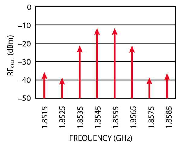
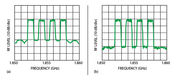
To validate the proposed predistortion linearizer, a power amplifier (STA1800-37, 5 W), developed for a base station, or a repeater for personal communication service (PCS) in Korea, was used. Schottky diodes are used in the reflection type harmonic generators. Figure 7 shows the linearization results for a two-tone signal. Note that the levels of the IM3 components were decreased by more than 30 dB and those of the IM5 components by about 20 dB. The performance of the linearizer is similar in the broad bandwidth and wide dynamic range of the power amplifier. Figures 8 and 9 show the output spectra of the amplifier with and without the predistorter for a CDMA and a CDMA.4FA signal, respectively. The spectral regrowth was improved by more than 10 dB for the 1FA and multi-FA signals. Figure 10 shows the ACPR versus input power for a CDMA signal using the predistorter.

Conclusion
A new predistortion technique, using reflection type harmonic generators, is proposed. This linearizer has been configured in a very compact circuit structure and the losses are very low. This circuit is able to control the magnitude and phase of each of the IM3 and the IM5 components individually.
Computer simulations and measurement results are presented to validate the proposed predistortion linearizer. The results show that significant cancellations of the IM3 and the IM5 components are achieved in the two-tone test. The CDMA test shows that the ACPR is improved by over 10 dB at an optimized average channel output power and the improvement is maintained over a broad range of the power levels. This predistorter can be easily linked to an appropriate adaptation control circuit because it uses only four control parameters for each harmonic generator. Adaptive control circuits can be conveniently added due to the compact size of the predistorer.

References
1. P.B. Kenington, High Linearity RF Amplifier Design , Artech House Inc., Norwood, MA 2000, pp. 351-420.
2. S.C. Cripps, RF Power Amplifiers for Wireless Communications , Artech House Inc., Norwood, MA 1999, pp. 179-218.
3. L. Reinhold, RF Circuit Design , Prentice Hall, 2000, pp. 352-357.
4. Y.C. Jeong, "A Design of Predistortion Linearizer Controlling the Individual Order of Intermodulation," Thesis, Sogang University, Seoul, South Korea, 1995.

Sang Won Kim received his BSEE from Sogang University, Seoul, South Korea, and is currently working toward his master's degree. His research includes PA design. He can be reached via e-mail at melanio@sogang.ac.kr.
Han Yu Cho received his MSEE from Sogang University, Seoul, South Korea, in 1982, and his PhD in electronics engineering from Sogang University in 2002. He has been a professor at Dong-yang Technical College since 1991. His research interests include microwave circuit analysis, design and amplifier linearization techniques. He can be reached via e-mail at hycho@orient.dytc.ac.kr.
Young Kim received his MSEE from Sogang University, Seoul, South Korea, and is currently working toward his PhD degree. He developed cellular and PCS linear power amplifiers at Samsung Electronics Co. Ltd. His areas of interest include the design of high power amplifiers and linearization techniques, and RF and microwave circuit analysis and design. He can be reached via e-mail at youngk@unitel.co.kr.

Ik Soo Chang received his PhD degree from Seoul National University, Seoul, South Korea, in 1982. He is now a professor at Sogang University. He has more than 20 years of experience in RF and microwave circuit design and is a member of IEEE. He can be reached via e-mail at ischang@ccs.sogang.ac.kr.
Won Woo Lee received his PhD degree in electrical engineering from Syracuse University, Syracuse, NY, in 2001. He is currently an assistant professor in the department of electrical engineering at the Korea Military Academy, Seoul, South Korea. His current interests lie in numerical analysis of scattering and radiation problems, and design methods of high power microwave devices. He can be reached via e-mail at wlee01@kma.ac.kr.