
The main criterion when an EM engineer uses modeling and design packages is that it should enable him to meet his daily challenges of designing new products that work in their intended environment. This is now becoming a reality with the advent of the Micro-stripes Version 6.1 3D-EM modeling and antenna design package (see Figure 1 ). This highly efficient Transmission Line Matrix (TLM) solver has been upgraded to fully exploit the advantages offered by 64-bit architecture, coupled with the ability to take advantage of multi-processor platforms.
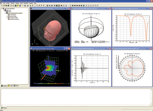
The software package harnesses the power of the TLM method in the time domain and offers it to the user through a design environment specifically for engineers. The salient performance parameters of a device, such as full S-matrix, radiation patterns, surface currents and field plots, are given in a project tree.
Key features include the incorporation of sub-cell models for wires, ports, circuits, slots, air-vents and thin film material, which provide substantial saving in model size and increased model efficiency. The software utilizes advanced multi-gridding technology, which includes automatic mesh generation and cell recombining in areas where fine mesh is not needed. It also benefits from a highly efficient and accurate TLM time domain solver that utilizes parallel processing for increased speed, together with enhanced post processing.
Sub-cell Compact Models
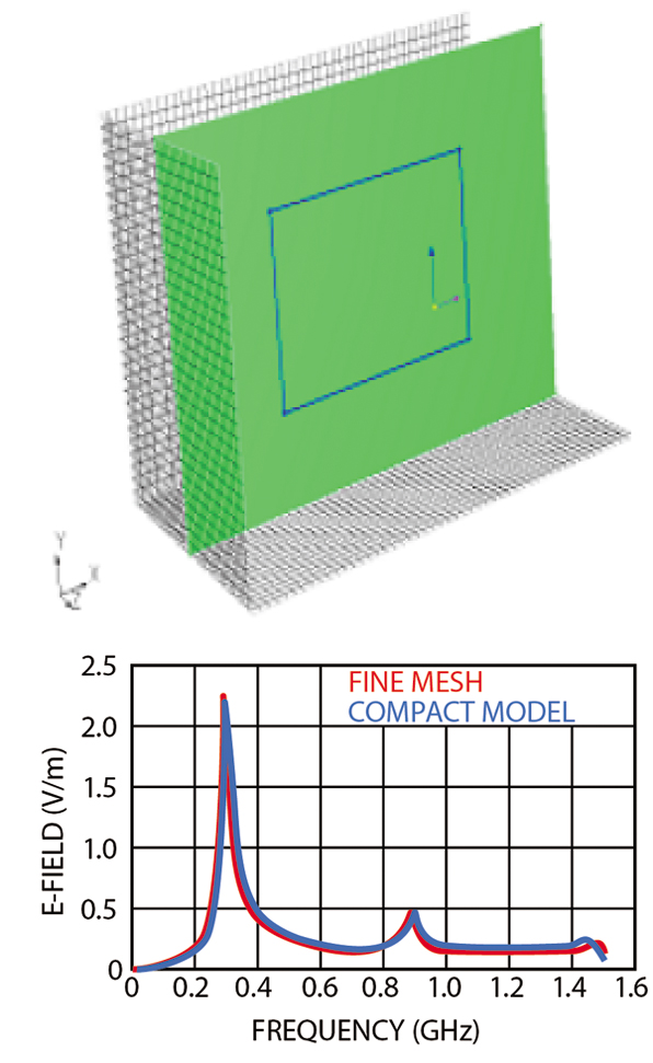
It is often the case for time domain volumetric solutions that small features, such as wires, slots and thin films must be finely meshed to fully capture their EM behavior. This introduces small mesh size, which has an impact on the overall central processing unit (CPU) time required for a solution. Enhancements to the TLM solver allow these fine features to be solved within a single cell through the introduction of compact equivalent circuits, which correctly capture EM behavior without compromising accuracy. This delivers a huge advantage as it increases solution speed and reduces the model size.
To illustrate the benefits of this feature, two examples are presented for the slot and thin film compact models. For the slot consider a metallic screen of 40 mm by 40 mm that has been punctured by a 2 mm wide rectangular slot, as shown in Figure 2 . The frequency domain solution obtained from the compact model and the full mesh model are given and show good agreement.
It is worth noting that the compact model was solved within 60 seconds and required 3 Mbytes of memory, while the full model required over 3 hours of CPU and 30 Mbytes of memory. The compact model also allows the slot space to be filled with lossy dielectric or magnetic material to simulate the presence of a shielding gasket.

The thin film modeling feature allows the antenna designer to account for the effects introduced by the presence of a plastic enclosure near the radiating element without suffering a huge penalty in CPU and storage requirements that will accrue from finely meshing the enclosure. This capability was crucial in checking the embedded antenna performance of a Bluetooth antenna in a laptop, as shown in Figure 3 .
64-bit Parallel Technology
The military, space and automotive industries have been early adopters of the 64-bit parallel EM technology offered by Flomerics, that is now allowing these users to undertake detailed and complex calculations they were not able to perform before and break the inherent 2 Gbyte model limit of 32-bit architecture. It is also possible to include frequency dependent material properties and allow designers to study the effects of different coatings on the stealth properties of the various platforms and gain substantial insight into their overall EM behavior through powerful visualization tools.
1g and 10g SAR Capability
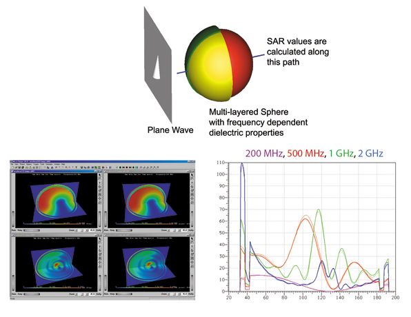
The capability of handling materials whose electrical properties vary with frequency through various dielectric dispersion models such as Debye and Lorentz has contributed to making Micro-stripes V6.1 particularly suitable for specific absorption rate (SAR) applications. A full database describing the electrical properties of human tissue as full frequency dependent models is included in the package. The basic data used for these models was obtained experimentally and characterizes the tissue over the DC to 20 GHz band.
The inherent ability of the TLM method to yield accurate results at dielectric boundaries, especially when the refractive index contrast is high, is shown in Figure 4 . It shows a multi-layered spherical phantom where each layer has been given frequency dependent electrical properties of human tissue. This phantom is then illuminated by an incident plane wave.
The total field solution along a path through this phantom can be calculated exactly using theoretical formulas at different frequencies. These values serve as a control to the field values computed using Micro-stripes. As shown, there is good agreement between the theory and the software.
A full Specific Anthropomorphic (SAM) homogeneous phantom is also included to allow antenna designers and handset manufacturers to perform SAR simulations. The new post processing allows the 1g and 10g SAR figures to be calculated. Figure 5 shows a typical SAR simulation for a handset antenna.
Other Features
The industry standard solid modeler kernel, ACIS, is used as the foundation for the geometry creation tool in the software, which has been enhanced with a powerful healing tool to allow easy interchange of files between different CAD packages. Among the file formats supported for import and export are SAT, IGES, STEP, STL and DXF. All the format translation tools are available within the standard package and are not sold as optional extras.
Post processing has improved in Version 6.1 and it is now possible to capture the near-fields from a radiating structure over a cylinder whose radius is set by the user. This data mimics the emission testing requirements within an electromagnetic compatibility (EMC) test facility if the radius is set at 3 or 10 m.
Another feature is the ability to locate monitor points (sense points) outside the meshed workspace to mimic EM probe points of a spectrum analyzer. These points can monitor all the field components in the time domain and thus allow full spectral data to be obtained from these points.

Conclusion
Micro-stripes V6.1 is a feature-rich, 3D, time domain code that delivers results through increased productivity. The package is presented as an EM design platform that harnesses the power of the TLM solver engine. The aim is to allow solver enhancements through compact models to be made available to users and pass on the benefit in the time they afford. These enhancements, combined with the new 64-bit solvers, will give users faster and more accurate solutions in the challenging world of virtual EM prototyping. Additional information may be obtained via e-mail at info@flomerics.co.uk.
Flomerics, Hampton Court, Surrey, UK Tel: +44 20 8941 88 10, fax: +44 20 8941 87 30, Web site: www.flomerics.com. Circle No. 300