
The design of a millimeter-wave antenna with a pencil-beam pattern is complicated when using a slotted waveguide and results in unacceptable dissipating losses, as high as 8 to 10 dB for a microstrip (RT duroid or Cu/PTFE substrate) distributor. This is why most submillimeter-wave antenna designers avoid traditional VHF solutions and turn to quasi-optics. This approach decreases the weight, dimensions and cost, and makes unnecessary the design of a hybrid waveguide-microstrip transition.

Zelubowski1 describes an original but complicated solution. The beam-forming network is designed according to the Hynes array rule.
It is based on a narrow parabolic horn, filled with a dielectric.
The emitting surface consists of two conducting surfaces with radiating slots made in one of them.
Unfortunately, this type of antenna cannot be manufactured inexpensively.

Denisenko, et al.,2 described a tree-shaped array with six printed circuit sub-arrays and a beam-forming network based on the Rotman lens.
This construction is also expensive because of the high precision mechanical work required. For both the antenna types mentioned, it is difficult to realize a tapered aperture distribution and a large ratio D/λ.

This article describes an inexpensive microstrip antenna with a simple waveguide distributor and proposes a method to model and design it. It provides a radiation pattern of a special form with a half-power beam equal to 1° in the azimuth plane. This transmit/receive antenna is intended for a circular-scanning radar.
Antenna Design and Construction
The distributor waveguide is excited in the H10 mode with a non-radiating slot in the middle of its broad side. This slot is used to couple with the radiating microstrip structure. Figure 1 shows the configuration of the antenna under consideration. Part 1 is the base, which includes half of the distributor waveguide (2). Part 3 is the microstrip printed circuit board. Part 4 shows the microstrip probes which couple to the waveguide. The removable part 5 includes the second half of the waveguide (6). A foam filler (7) covers the microstrip radiators and the whole assembly is covered by a radome (8).

The waveguide is UG-387/U. A load terminates one end of the waveguide; the other end has a flange to connect to the input source. To provide stability, the coupling to the radiating elements was designed to be 10 percent of the input power. The losses in the partially dielectric-filled waveguide were taken into account. The microstrip printed circuit board was made by a two-sided photolithographic method. The groundside of the microstrip board overlaps by 1 mm the reference level of the microstrip side, which is then aligned with reference marks on the base structure.
Radiation Pattern Synthesis
The first step in determining the azimuth plane pattern is to define the array spacing on the basis of the propagation constant in the partially dielectric-filled waveguide. The HP HFSS® v.5.6 modeling software permits simulation of this special waveguide section. In order to prevent a large standing wave ratio within the operating frequency region, the array spacing should be made slightly larger than λ/2. This may cause a few degrees beam tilt.

The quantity Nx of radiators and the amplitude distribution Ixn are chosen using a cosine-squared on pedestal function. This provides the required beamwidth and side lobe level of 1° and 28 dB, respectively. The microstrip part of the antenna is made in accordance with the design of a resonant series-fed array. Such linear arrays allow the realizing of a wide set of amplitude and phase distributions. Here, the aperture synthesis with a cosecant pattern was realized in the E-plane. Reference to the Woodword-Lawson method, which uses partial functions, must be made. The use of these functions is possible here because pattern oscillations are permitted. An example of a Woodword-Lawson function is (sin πu)/πu, where u = D/λ0(sin θ - sin θ0). Figure 2 shows a comparison of the array topology for Dolf-Chebychev and cosecant distributions. In the first case (Dolf-Chebychev), the radiator size is made on the basis of well-known quasi-static approximations,3 which express the dependence of the radiator input impedance on its size. In the second case (cosecant), it is necessary to correct this dependence using a numerical program such as Microwave Office v.3.4, as most of the radiators have widths comparable with the feeding microstrip.
In order to verify the results of this synthesis, it is necessary to revert to the initial interpolation pattern by using the cosecant linear array. Consider the amplitudes Iy m and phases Ψm, coordinated with the radiator number m, where m = 0...Nym. Notice that the steps of this array contain both a constant Lp (average radiator length) and variable components (distance between patches) Δdm, which is the source of the phase distribution in the microstrip series-fed array. Thus, the patch coordinates include two components: m.Lp and a recurrent sum S (Δdm,m).
The theoretical beam pattern in the elevation plane fy(θ), which takes into account the diagram of the single radiator, is shown in Figure 3. This pattern satisfactorily demonstrates the validation and appropriate use of the Woodword-Lawson method (approximation in the sense of least-squares for selected Ny pattern points).


where

Numerical Modeling Method of Microstrip Board Profile Dip in Waveguide

The recurrent formulas for coupling coefficient calculations for a linear series-fed traveling wave array are widely known and easy to derive. The distribution of the coupling coefficients Kn, corresponding to an amplitude distribution Ixn, is shown in Figure 4. Consider now a model plate consisting of ten linear arrays, which are fragments of the future antenna plate with feeder strips of equal length and consequently of equal connections. Its radiated power Prn for the above range of Kn fluctuations will have the form

where
j = number of model plate element, j = 1...10
n = number of series-fed array, n = 1...110
Thus it is necessary to define the analytical dependence of a ten-element model plate level dip with its free space radiating power H (Prn). The solving of a problem concerning the microstrip profile "ridge" providing the given amplitude distribution Ixn is obtained by substituting the value of Prn as an argument of the function

This problem can be solved in the framework of structural modeling programs (such as HP HFSS). The numerical solution of electrodynamics problems requires some approximations. In this case, it is necessary to replace a sufficiently complex series-fed array by a single microstrip radiator. The model plate consisted of ten microstrip radiators spaced at λw/2 intervals and dipped in the waveguide by 0.0, 0.1, 0.2, ...0.6 mm consecutively. The S-parameters are calculated for each case. The model plate scheme from HP HFSS is presented in Figure 5.
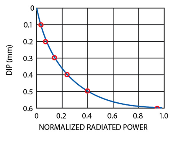
The result of the modeling is the functional relation between the model plate dip level and the normalized radiated power, taking into account the return and dissipated losses (see Figure 6). The radiating power is uniquely determined by the coupling coefficients in Equation 3.
Finally, if the dip levels of the Nx patch (with the radiating power Prn (n = 0...Nx-1)) of the linear array coupling probes in the waveguide obey Equation 4 (see Figure 7), then this array provides the required side lobe levels of -28 dB.
(5)
Hn = H(Prn)
Experimental Results
In accordance with the described method, an antenna operating at 76.5 GHz was simulated and fabricated. The 260 x 60 mm printing board contained 2310 radiators - 110 horizontally and 21 vertically oriented, which were necessary to provide a 1° azimuth beamwidth and create the special form of pattern required for the elevation angle. The radar unit consists of identical transmit and receive antennas, and is shown in Figure 8.
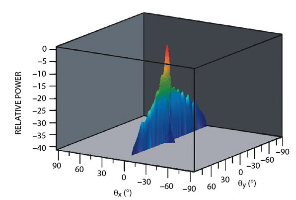
The two boards are placed in a box connecting the waveguide distributors and the mounting elements, forming a package 280 x 160 x 22 mm. The gain of the antenna was 29.7 dB, thus the total antenna losses are less than 5.3 dB, as the calculated directivity is 35 dB according to the pattern of Figure 9. A study of the antenna losses permits the following evaluations:
- The dielectric and ohmic losses in the microstrip are 2.7 dB; this figure was obtained with the use of the "Mwi.exe" program, recommended by Rogers Co.
- The radiation losses are 1.6 dB; the evaluation of these losses was made on the basis of analytic comparison between theoretical and experimental beam patterns, both in the main lobe and beyond its limits, accounting for background radiation.
- The losses in the waveguide distributor are 1 dB.
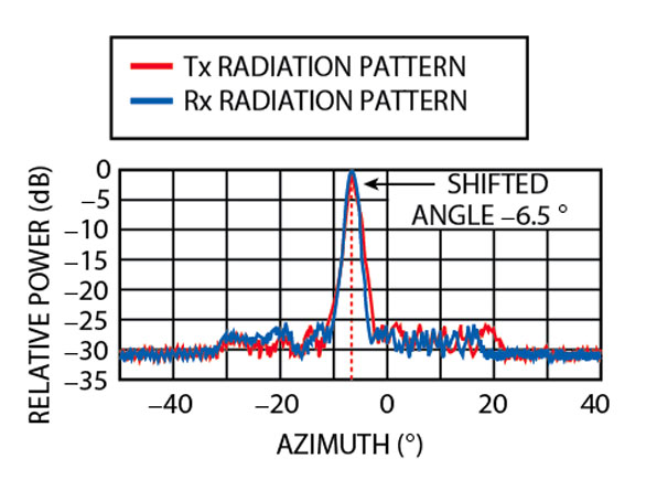
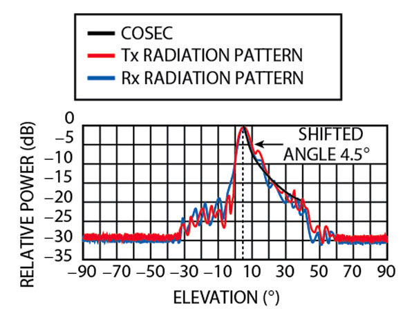
The antenna characteristics were measured at the waveguide input and the patterns were taken as well, as shown in Figures 10 and 11. The technical performance of the antenna is given in Table 1. The gain is close to the one required and the pattern corresponds to the results of the synthesis. In the operating range, 76.5 ±0.2 GHz, the direction of the beam maximum, beamwidth and side lobe level are invariable.

Conclusion
The multiple-element antenna (n = 2300) was manufactured on the basis of inexpensive microstrip technology with a beamwidth of approximately 1° and low side lobe levels. A simple engineering solution for a waveguide distributor with low insertion loss in the operating range was found. A simulation model is offered. The antenna tests have demonstrated high agreement between measured and calculated values of propagation constant in partially dielectric-filled waveguides and coupling probes (the measured deviation angle of the beam coincide exactly with the calculated one), SWR, gain and pattern parameters.
However, it was found that the position of the first zeros in the patterns is not exactly as predicted. This non-determined character of side lobes in the azimuth plane is apparently connected with an error in antenna phasing, caused by an incomplete mathematical model. Using HP HFSS as the main program to calculate the antenna geometry is as time-consuming as it is effective. With the numerical calculation of an antenna fragment (not a simplified electrodynamics construction), a fuller account of the influence of the array edges and the mutual coupling of the microstrip structures on antenna parameters could be achieved. However, the main goal of this work was obtained. The pencil-beam microstrip antenna with low side lobe levels was manufactured and recommended for serial production.
References
1. S.A. Zelubowski, "Low Cost Antennas Alternatives for Automotive Radars," Microwave Journal, Vol. 37, No. 7, July 1994, pp. 54-63.
2. V.V. Denisenko, A.G. Shubov, A.V. Majorov, E.N. Egorov and N.K. Kashaev, "Millimeter-wave Printed Circuit Antenna System for Automotive Applications," 2001 MTT Symposium Digest, Phoenix, AZ, Vol. 3, 2001, pp. 2247-2250.
3. R.A. Sainati, CAD of Microstrip Antennas for Wireless Applications, Artech House Inc., Norwood, MA 1996.
 Victor Volkov received his PhD degree in physical electronics from St. Petersburg Polytechnic Institute in 1985. He now works as a chief scientist at the Scientifically Research Institute. He can be reached via e-mail at volkova@mail.wplus.net.
 Michael Parnes received his PhD degree in microwave techniques from St. Petersburg Electromechanical Institute in 1989. From 1981 to 1990, he worked at the Research Institute as an engineer. In 1990, he set up his own enterprise designing and producing microstrip antennas. His research interests include antenna arrays for communication and radar. He can be reached via e-mail at mdparnes@online.ru.
 Victor Korolkov graduated from St. Petersburg Polytechnic Institute in 1983. From 1983 to 1998, he worked at the Scientifically Research Institute as a research engineer for microwave magnetic electron devices. Since 1998, he has been engaged in the development of passive and active antenna arrays. He can be reached via e-mail at vdk@online.ru.