
The International Telecommunication Union (ITU) standard Wideband Code-Division Multiple Access (WCDMA) was derived from code-division multiple access (CDMA), and is officially known today as IMT-2000 direct spread. It is a third-generation (3G) mobile wireless technology offering much higher data speeds to mobile and portable wireless devices than commonly offered in today's market. WCDMA can support mobile/portable voice, images, data and video communications at up to 2 Mbps (local area access) or 384 kbps (wide area access). The input signals are digitized and transmitted in coded, spread-spectrum mode over a broad range of frequencies.
When 3G networks are fully deployed across Europe, mobile Internet access will provide users with many types of new services and content over a wide range of different networks and user devices. These services, many of which have yet to be developed, will be capable of accommodating user's personal preferences, location and circumstances at a particular moment in time.
However, before the 3G dreams can be fully realized, the industry must wait for the public to decide whether they can afford the extra services the bandwidth will provide. Clearly, that will be dependent upon the content available, and simply browsing the Web faster will not be sufficient to generate public interest. While the content debate continues, the task of installing a viable WCDMA infrastructure that will enable 3G connectivity has to be addressed.
To achieve this, the engineering challenges are formidable and, over the past decade, the role of the RF systems engineer has made a notable change. Up until the 1990s most system engineers dealt with requirements and functions by using a black box approach to design. Today, however, the demands being placed on the designers to reduce power, while at the same time improving performance, means that there is also a need to know what goes on in every black box. Only then can the various parameters be tuned and optimized to allow the overall system requirements to be met.
Design software has come a long way, and there are software tools available that allow the system engineer to go into far more detail, have access to accurate simulations, and handle far larger communications chains than ever before. Unfortunately, there is a price to pay, and that price only becomes apparent when a team of engineers tries to pass the various aspects of a system design between groups of design specialists.
Power Budgets
Computer modelling plays a vital role in all system design but, surprisingly, one of the most widely utilized tools today is the Microsoft spreadsheet program - Excel. It is an excellent tool for keeping track of parameter budgets, but the fundamental drawback is that it is not an engineering tool.
For instance, take the example of a transmit/receive (Tx/Rx) channel in a WCDMA base station, where the system designer needs to define the RF power, filter characteristics, signal-to-noise ratios, local oscillator stability and response of a phase-locked loop. A spreadsheet allows the designer to build up a simple description of the Tx/Rx path, with each module, such as filter, amplifier and modulator, being described by one spreadsheet cell, allowing access to a basic budget analysis, highlighting points of high noise levels, or highlighting a need for amplification.
Many small RF design teams of less than 10 to 15 engineers use the spreadsheet approach. Undoubtedly, this method does the job, provided the system engineers using this approach have an in-depth knowledge of circuit design, in addition to their expertise in systems engineering. More commonly, however, the number one reason for using Excel is because it is perceived as being free, as it comes bundled with the office PC in many cases. The cost of ownership of this type of software tool is very low, but for complex system work it often requires a disproportionate amount of time and effort to make it productive.
While Office spreadsheets are fine for tracking discrete values, they are poor, or even useless, for handling S-parameters or the type of equations used by RF systems engineers. So, if spreadsheets are not really suitable, what is? Some commercially available RF systems software packages have a built-in library of modulation schemes, RF parts such as filters and mixers, as well as functional parts, including digital logic gates, probes and switches.
These packages allow the designer to have greater control of the characteristics of each part, and to make them as realistic as possible. By following the analysis reports available from such tools, bit error rate (BER) plots, eye diagrams and spectral plots can ensure that a system will be designed for optimum performance.
Some pure mathematical tools currently available will allow an RF engineer to model functional blocks in the transmit/receive channel of a WCDMA base station, for example, but they can also allow the creation of impossible circuits. For instance, zero impedance transmission lines, or unfeasibly large capacitors, can be required. Therefore, if meaningful results are to be generated, the user must be both a component designer and a system designer.
Plugging tools together from multiple vendors always sounds easy, but in practice this task often proves to be very difficult and time consuming. Multivendors are often chosen because companies believe they can save money by "shopping around" and purchasing what they need. It is only once the tools have been delivered that the real meaning of seamless integration becomes apparent.
Mixed-mode Simulation
Seamless integration - that well-used marketing phrase - usually means: "Spend only a few weeks getting your software engineers to write conversion scripts in order to make all the tools work together!" The problems usually arise when RF engineers, who use and work with S-parameters, need to export their system level designs to digital component engineers. The component engineers do not generally have a problem with S-parameters, but tend to use SPICE models in their design environment.
The challenge for the tool vendors has been to develop the required interfaces that will enable the export of S-parameters into SPICE libraries, and vice versa, to enable designs to be passed between system level and component design teams.
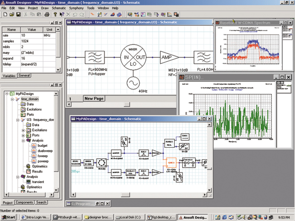
To illustrate how this can be achieved consider the Ansoft Designer interface in which the mixed-mode simulation environment utilizes I and Q baseband signals that are generated with the Rohde & Schwarz WinIQSim software package. The capability offered enables engineers to apply RF signals from many of today's communication standards, including 3GPP WCDMA, TD-SCDMA, Bluetooth, Hiperlan/2, IEEE802.11b and CDMA2000 directly to their circuit and system simulations. Having the simulation engine within the environment's interface allows engineers to use real-world parameters within the function block library, and therefore, unlike a pure mathematical tool, any attempt to use a circuit value outside of a usable range will be restricted.
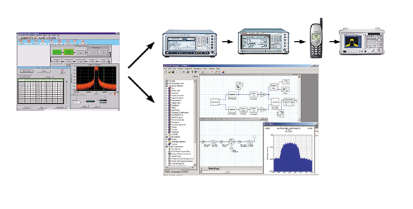
Users can generate arbitrary waveforms by modifying the value of parameters and impairments affecting the waveform. Figure 1 shows a typical data capture flow. These user-specified waveforms may then be stored as signal source library components for use in driving the mixed-mode simulation environment (see Figure 2).
In this way RF designers and system architects can simulate communication systems under the same conditions used in hardware testing and product development.
Through access to the latest communication standards, designers have the advantage of qualifying component and system specifications under actual operating conditions much earlier in the design process.
The software permits the calculation of I and Q baseband signals, which are in turn used with signal generators to excite communication transceiver radios.
Having access to a library of built-in RF system level components is a major advantage. Amplifiers can be included that model both the linear region and intermodulation distortion (IMD) created by the nonlinear transfer characteristic, voltage-controlled oscillators that include phase noise characteristics, mixer models that incorporate spurious products, modulators and demodulators including IQ, AM, FM and PM, black boxes that support importing of S, Y and Z parameters, noise and nonlinear measured or software generated data can be included.
In mixed-mode simulation, component specification can be as simple or as complex as the user demands, with components initially being specified with a few key parameters. This enables engineers to quickly build a system model for "what if" analyses. As the design progresses and more data become available, it can be included to refine the simulation. For example, an amplifier can be modelled several ways - gain, P1dB and IP3, frequency, temperature and/or power dependent S-parameters, and AM-AM and AM-PM data. In addition, imported data can be used to model inputs, arbitrary modulation methods and noise sources.
Feed-forward Example
In the example given below, a feed-forward amplifier with a WCDMA input is discussed. First, the software implements the physical layer of WCDMA frequency division duplexing (FDD) with all physical channels defined by 3GPP. Parameters such as symbol rate, channelization code, channel power, channel data, channel state, and transmit power control bits and scrambling codes are independently settable for each code channel base station or mobile station.
A 3GPP mobile station can operate in three different modes:
- Physical Random Access Channel (PRACH) only, where the mobile station generates a single PRACH, which is used when a call is set up from the mobile to the base station.
- Physical Common Packet Channel (PCPCH) only, where the mobile station generates a single PCPCH. This channel is used for the transmission of packet-oriented services (such as SMS).
- Dedicated physical control and data channels (DPCCH + DPDCH) is the standard mode for speech and data transmission.
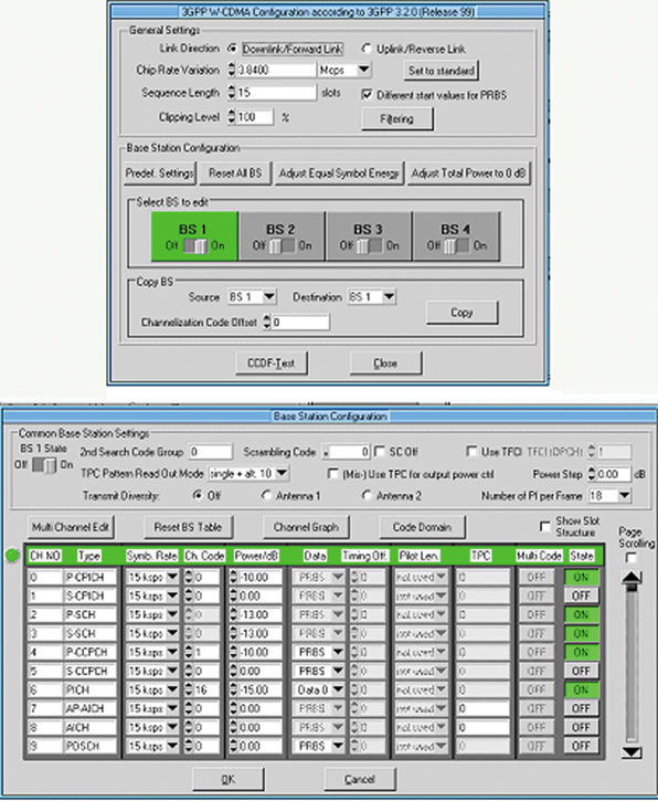
Then the mobile station generates a control channel (DPCCH) and up to six data channels (DPDCH), depending on the required data rate. Taking the example of WinIQSim and Ansoft Designer, the signal and response of up to four mobile stations can be simulated, each operating in one of the modes - PRACH only, PCPCH only, DPCCH and DPDCH (see Figure 3).
While base station configurations are more complex than mobile station modes, not all downlink channels are essential for simulation or testing. Using typical configurations will provide adequate simulation conditions for understanding device or system behavior. A basic base station signal contains the ever-present control channels required for synchronization and a varying number of dedicated physical channels (DPCH). The number of DPCHs and their symbol rates depend on the number of connections and the required data rates. If high data rates are required, several DPCHs can be linked together and transmitted to one and the same mobile (multicode state). For base station simulations, the software generates signals of up to 512 data channels distributed to a maximum of four base stations with 128 code channels each.
Statistical Properties of 3GPP Signals
The superposition of many code channels may lead to very high crest factors in the WCDMA sum signal. Because crest factor influences the linearity requirements of system components, particularly the power amplifier, it is important to simulate designs with statistically correct signals. The signal's statistical properties - expressed in the complementary cumulative distribution function (CCDF) - generally depend on four parameters: the number of code channels; the selection of channelization codes; the correlation of the user data; and the timing offsets between code channels.
The mixed-mode simulation method allows users to fully investigate intermodulation distortion or spectral regrowth due to the nonlinearity of a power amplifier at the circuit level or behavioral (system) level. Also, circuit envelope analysis provides the capability to look at spectral waveforms, eye diagrams, constellation plots or adjacent channel power ratio (ACPR) as a function of any swept parameter, including power, bias and impedance tuning. Signal-processing probes allow direct plotting of crest factor, error vector magnitude (EVM) or CCDF.
Multicarrier WCDMA and Multistandard Signals
The capability of the software to support generating and simulating multicarrier and multistandard signals is critical for tests on amplifiers and other components with multicarrier signals. The single WCDMA carriers are generated separately with the 3GPP WCDMA system and then mixed in the multicarrier mixed signal system.
This function is not limited to multicarrier WCDMA. Mixed systems (that is WCDMA carriers combined with GSM or other systems) are also possible. These features can be used to simulate transmitters of multisystem base stations. Such units will become more important as they provide integration of new WCDMA technologies on existing networks.
Conclusion
If RF engineers and system architects are to achieve first-pass designs in an evolving, time critical market such as WCDMA, then it is no longer practical to rely on "home brewed" tool chains from several software vendors. This is because the time needed to integrate all the tools together, and gain sufficient levels of confidence will be too long. Only a design environment capable of fully modelling high frequency component behavior offers the greatest likelihood of success.
The partnership between an EDA vendor with its designer software environment, and a test and measurement company with its software combines accurate signal generation with RF modelling and simulation. It provides a fusion of real-world data with advanced electromagnetic analysis for designing at component, circuit and system levels.
While it is common knowledge that a screwdriver can be used as a lever, or a chisel, it's not the right tool for the job. Similarly, it is rather like using a spreadsheet to design 3G communications. Given enough time and effort a spreadsheet will serve a purpose, but if your competitor has a cost-effective tool that is right for the job, and your team does not, do not expect to win the time to market race.
Charles Blackwood earned his BSc degree in communication engineering from the University of Kent at Canterbury. He is currently the Northern European sales manager for Ansoft Corp. Europe and is based in the UK. Before working for Ansoft, he worked for several telecommunication companies, including Siemens and Matra.