
Modern frequency synthesis uses a combination of frequency multiplication and frequency division to generate the required data and carrier signals for microwave radio and radar applications.

Frequency multiplication increases the carrier frequency while increasing the phase noise of the carrier by 20log(N), where N is the multiplication factor. Conversely, frequency division decreases the carrier frequency and changes the phase noise of the carrier by 20log(1/M), where M is the division ratio.
For the most part, frequency dividers are used in a phase-locked loop (PLL) to divide the voltage-controlled oscillator (VCO) output frequency down to the reference frequency in order to achieve phase/frequency locking.
These devices are traditionally digital circuits and for high divide ratios (greater than 16) operate at input frequencies less than ~2 GHz. At higher frequencies, digital frequency dividers are available in binary division ratios (/2, /4, /8...) up to approximately 14 GHz.
A new class of GaAs/InGaP heterojunction bipolar transistor (HBT) active frequency dividers offering odd division ratios (/3 and /5), high input frequency (up to 8 GHz) and wide input power range (-15 to +10 dBm) are now available in low cost plastic packages providing the designer with more flexibility in synthesizer architecture.

Frequency multipliers, on the other hand, are most commonly used after the VCO to increase the carrier frequency to the radio or radar transmit/receive frequency. Various devices are utilized to achieve frequency multiplication, including Schottky diodes, step recovery diodes, balanced rectifiers (frequency doublers) and saturated amplifiers. The advantages and drawbacks of each approach are well known.
A new class of GaAs/InGaP HBT active multipliers offering conversion gain, wide input power range (-15 to +10 dBm), high output frequency (up to 16 GHz) and high multiplication factors (x 4, x 8 and x 16) are now available in low cost plastic packages that will dramatically simplify the design and implementation of X- and Ku-band synthesizers.
Four new active frequency multipliers have been added to the company's family of surface-mount frequency doublers. Figure 1 depicts the frequency coverage of the passive and active frequency multiplier line. The models HMC370LP4 and HMC443LP4 are active x4 frequency multipliers with output frequencies at X- and Ku-band, respectively.
The models HMC444LP4 and HMC445LP4 have output frequencies in the 10 to 11 GHz frequency range. Inspection of data reveals that the new active multipliers are suitable for the OC-192 fiber optic market, military radar and the microwave radio markets.
The key performance parameters of the active multipliers are summarized in Table 1. The HMC445LP4 multiplier will convert an OC-12 clock frequency directly to OC-192 with up to +7 dBm output power operating from +5 V and consuming only 78 mA of current.
Similarly, the HMC444LP4 and HMC443LP4 devices will convert OC-24 and OC-48 clock frequencies to OC-192 while using only 68 mA and 52 mA of current, respectively. All four active multipliers are supplied in 4.0 x 4.0 x 1.0 mm leadless surface- mount QFN plastic packages compatible with automated assembly and reflow soldering processes.

Table 1 | ||||||
Part |
Function |
Input |
Output |
Input |
Output |
SSB |
|
HMC445LP4 |
x16 active |
618.75 to 687.50 |
9.9 to 11.2 |
-15 to +5 |
+4 to +7 |
-130 |
|
HMC444LP4 |
x8 active |
1237.5 to 1400.0 |
9.9 to 11.2 |
+15 to +5 |
+3 to +6 |
-136 |
|
HMC443LP4 |
x4 active |
2450 to 2800 |
9.8 to 11.2 |
+15 to +5 |
+1 to +4 |
-142 |
|
HMC370LP4 |
x4 active |
3600 to 4100 |
14.4 to 16.4 |
+15 to +5 |
-4 to 0 |
-140 |
HBT Active Multiplier Advantages
Active multipliers designed in GaAs/InGaP HBT technology operate on single positive (+5 V) bias, with low current (< 80 mA) and low residual phase noise (-130 to -140 dBc/Hz at 100 kHz) at frequencies > 16 GHz. The input and output of the HMC445LP4 multiplier is single-ended, as shown in Figure 2. The only required external component is a bypass capacitor on the Vcc pin.
The x16 architecture is implemented as a series of x2 active multiplication stages. Each stage has integrated filtering for optimum subharmonic performance.
This filtering circuit results in the narrow-bandwidth nature of the active multiplier line and is responsible for the excellent harmonic and subharmonic rejection of > 20 dB, as shown in the output spectrum of Figure 3.

Since these filtering circuits are designed specifically based on the input frequency band, they can be easily scaled to create active multipliers operating at other frequencies.
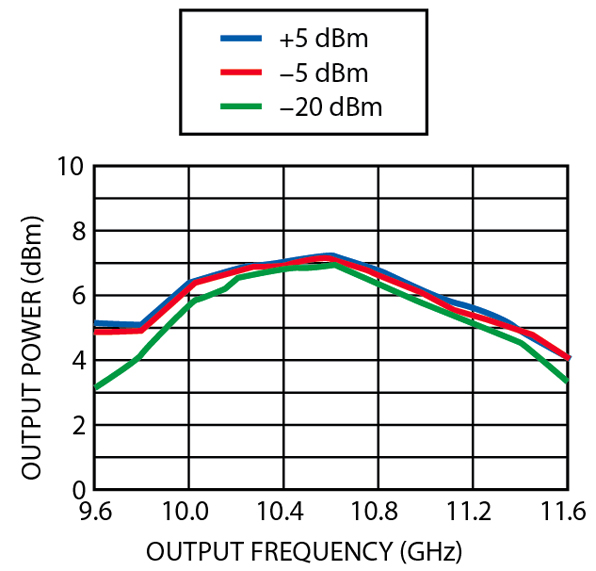
Output power of the HMC445LP4 device is flat over a wide range of input power, as shown in Figure 4.
The insensitivity of output power to input power variation results in natural AM suppression and coupled with excellent power flatness vs. temperature further simplifies synthesizer architecture by minimizing the need for limiting amplifiers or gain control.
An Example 16 GHz Application

A typical application of the HMC370LP4 active x4 multiplier as an LO generator for a microwave radio is shown in Figure 5.
LO chains for microwave radios in the 28 to 32 GHz band typically begin with an L-band source that is frequency multiplied to the transmit band through successive stages of amplification and frequency doubling. With the availability of low cost subharmonically pumped mixers for the 28 to 32 GHz band, the designer is only required to generate a 14 to 16 GHz LO signal at -5 dBm.
A passive doubler solution to this problem would require three stages of amplification/doubling with each successive stage increasing in cost due to the drive level and filtering requirements. With the wide input drive range of the HMC370LP4 multiplier, the entire chain can be replaced with one passive doubler and one active x4 multiplier with no additional amplification or filtering.
The company has expanded its line of digital frequency dividers with the addition of the models HMC437MS8G (/3) and HMC438MS8G (/5) that operate over a DC to 7 GHz frequency range.
The key performance parameters of the company's family of GaAs/InGaP HBT frequency dividers are summarized in Table 2.
The HMC437MS8G and HMC438MS8G operate from a single +5 V supply, have differential inputs/outputs and consume 69 and 80 mA of DC current, respectively.
Both new dividers are supplied in 3.0 x 4.9 x 1.0 mm surface-mount plastic packages compatible with automated assembly and reflow soldering processes.

|
Table 2 | ||||||
|
Part |
Function |
Input |
Output |
Input |
Output |
SSB |
|
HMC364S8G |
/2 |
DC to 12.5 |
DC to 6.25 |
-10 to +5 |
-8 to +5 |
-145 |
|
HMC437MS8G |
/3 |
DC to 7.0 |
DC to 2.60 |
-10 to +10 |
-4 to -1 |
-153 |
|
HMC365S8G |
/4 |
DC to 13.0 |
DC to 3.25 |
-15 to +10 |
+2 to +5 |
-151 |
|
HMC438MS8G |
/5 |
DC to 7.0 |
DC to 1.60 |
-12 to +12 |
-4 to -1 |
-153 |
|
HMC363S8G |
/8 |
DC to 12.0 |
DC to 1.50 |
-15 to +10 |
-9 to -6 |
-153 |

Digital dividers designed in GaAs/InGaP HBT technology operate on single positive (+5 V) bias, with low current (< 80 mA) and low residual phase noise (-145 to -153 dBc/Hz at 100 kHz) at frequencies up to 13 GHz.
The input and output of the HMC437MS8G and HMC438MS8G dividers feature differential inputs, as shown in Figure 6, but can be operated single-ended as well.
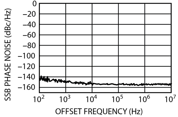
The low residual output phase noise and wide input power operating range are shown in Figures 7 and 8The output waveform of the HMC438MS8G divider is shown in Figure 9
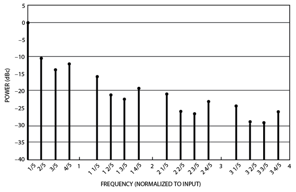
The 40 percent duty cycle results in an output frequency spectrum that has low (< -10 dBc) harmonics (Figure 10 ). In sharp contrast, a digital counter set to divide by five typically maintains the input carrier pulse width and hence has approximately a 10 percent duty cycle resulting in the rich harmonics shown in Figure 11 . Since the fifth harmonic of the output is also equal to the input frequency, the HMC438MS8G device has excellent feedthru suppression, as shown in Figure 12 .
An Example 5 GHz Application
A typical application of the HMC437MS8G /3 divider as an LO generator for a mobile phone base station is shown in Figure 13

LO chains for base station applications typically begin with a UHF VCO locked to a crystal frequency source that is frequency multiplied and amplified to the transmit/receive frequency.
With the availability of low cost, low noise C-band VCOs and high frequency dividers, the same LO signal can be generated by a C-Band VCO and frequency division.
In the example shown, a 5.4 GHz VCO output directly drives two successive /3 dividers to create the required 600 MHz LO frequency. The entire frequency generation chain consists of three low cost plastic-packaged components with no intermediate amplification or filtering stages.
The 600 MHz LO phase noise is shown in Figure 14

The VCO phase noise (top curve) is reduced through frequency division by 20log(1/9) = -19 dB. At carrier offsets greater than 1 MHz, the divider residual phase noise (bottom curve) limits the output phase noise to approximately -154 dBc/Hz.
Conclusion
A family of active frequency multipliers and frequency dividers has been introduced that allows the synthesizer designer to take new approaches to solving traditional microwave radio and radar application problems.
These GaAs/InGaP HBT devices are available in low cost plastic packages operating from single +5 V supplies. Conversion gain and excellent harmonic/subharmonic suppression minimize external support circuitry.

Product samples and connectorized evaluation boards are available on request directly from the factory or online at www.hittite.com.
Hittite Microwave Corp., Chelmsford, MA (978) 250-3343. Circle No. 303
