Double-balanced mixers are used extensively in transmitters and receivers. For frequencies below 5 GHz, the designs are normally realized using ferrite-based transformers, because they are very compact and their technology is mature.

As the operating frequency increases, distributed element baluns become smaller in size and more attractive.
Semiconductor-based mixers are the most compact. However, changing the design is very time consuming and expensive. Therefore, these mixers are generally targeted for high to super-high volume applications.

Blue Cell™ low temperature co-fired ceramic (LTCC)-based mixers are small in size, lower in cost and can be customized to meet various needs. They are easier to customize than semiconductor mixers and are ideal for moderate to high volume applications.
A series of Blue Cell™ LTCC-based mixers have been designed and are being offered as standard catalog products.
Blue Cell LTCC
Blue Cell LTCC technology provides the means to produce multi-layer circuits with ceramic substrate tapes. Conductive, dielectric and resistive pastes are applied on each ceramic sheet or tape, then numerous sheets are laminated together and fired (often in a precisely controlled oven or kiln) in one step.

The resulting design is a hermetic, monolithic structure. A typical Blue Cell LTCC structure is illustrated in Figure 1 and consists of multiple dielectric layers, screen-printed or photo-imaged low loss conductors, embedded resistors and capacitors, and via holes for interconnecting the multiple layers.
Each layer can be inspected before firing to replace damaged circuits and improve yield. Because firing takes place at low temperatures, typically about +850°C, low resistivity conductor materials, such as silver and gold, can be used instead of the molybdenum and tungsten materials typically used with high temperature co-fired ceramic (HTCC) processes.

Since Blue Cell LTCC is a repeatable process, it can reliably produce large quantities of RF and microwave components measuring a fraction of the size of components fabricated with conventional substrate materials.
To practically and cost-effectively apply Blue Cell technology, a series of sophisticated three-dimensional computer models have been developed using the latest electromagnetic (EM) simulation tools. These proven computer models allow new and custom LTCC components to be developed quickly, economically and reliably, with a high degree of first-pass design success.
Blue Cell LTCC technology yields a highly integrated, surface-mount module that can in turn be used as a platform to mount active components, such as transistors and monolithic amplifiers, to form a miniature multifunction assembly.

The resulting Blue Cell LTCC design is a multi-layer, three-dimensional design, such as that shown in Figure 2 , that is considerably more compact than a traditional, planar microwave component. High level integration allows Blue Cell LTCC components to be packed within a miniature, surface-mount package, eliminating the need for many external components.
In addition, Blue Cell LTCC designs can employ circuit elements in die form for further reductions in size. Since the ceramic materials used in Blue Cell LTCC designs are inherently temperature stable, the need to compensate for variations in temperature is greatly reduced.
Construction

Figure 3 is a schematic of a wide bandwidth double-balanced mixer whose intermediate frequency response extends to DC. The actual mixer design is patent pending. Baluns T1 and T2 are implemented using transmission line baluns distributed over multiple layers.
Proven reliability Schottky barrier diodes are used as mixing elements. Solder-plated leads are welded using a patent-pending process to the bottom of the LTCC board to provide interface to the surrounding circuit.
Electrical Performance

The temperature sensitivity of the material used in LTCC generally results in negligible variation of electrical performance. Figure 4 shows the conversion loss of the MCA1-24 mixer as a function of frequency and temperature.
These mixers are specified to operate over -55° to 100°C and are suitable for most commercial and military applications. Variation of conversion loss with LO power is basically a property of the semiconductor mixing elements and circuit design. Figure 5 shows LO-to-RF (L-R) isolation vs. frequency and temperature.
Note that the variation with temperature is negligible. Variation of isolation with LO power is typically less than ±3 dB. L-R isolation is typically in excess of 40 dB to 1.5 GHz and in excess of 30 dB over the rest of the range. This characteristic is very useful when these mixers are used in image reject, single-sideband and I/Q mixers.

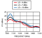
Figure 6 shows the LO-to-IF (L-I) isolation of the same mixers with temperature. Note the L-I isolation is greater than 20 dB over most of the range and temperature variation is negligible. Figure 7 shows the IP3 of the mixer.
This mixer has approximately 15 dBm or higher IP3 at 1 GHz. Figure 8 shows the mixer's IF response and Figure 9 demonstrates the 1 dB compression performance. Note the input power required for 1 dB compression is typically around 1 dBm.
A series of mixers were developed to cover the 300 to 6000 MHz frequency range. For example, model MCA1-24 covers the frequency range 300 to 2400 MHz and operates with 7 dBm of LO power. Models MCA1-24LH and MCA1-24MH cover the same frequency band, except they operate with 10 and 13 dBm LO power.

Higher LO power generally results in higher 1 dB compression and IP3. Table 1 summarizes the performance of these and other mixers developed using LTCC.
Conclusion
A series of double-balanced mixers has been developed to cover the 300 to 6000 MHz frequency range. These mixers have a low height profile of 0.065", a small 0.25" x 0.30" size and are temperature insensitive.

Mini-Circuits,
Brooklyn, NY (718) 934-4500,
www.minicircuits.com.
Circle No. 302
