
Technical Note
Coping with Hidden Spurious Harmonic Modes in the Design of Low Pass Corrugated Waveguide Filters
Hidden spurious harmonic modes in corrugated waveguide filters are investigated from both theoretical and practical points of view. It has been found that multiple mode couplings occurring at more than one place in a filter system cause the hidden spurious modes. An effective simulation scheme is introduced here to predict the hidden spurious modes based on a logical and methodical physical interpretation. The theoretical mechanism and proposed simulation scheme are both validated through a direct measurement and full-wave electromagnetic simulation.
Ke-Li Wu
The Chinese University of Hong Kong
Dept. of Electronic Engineering
Hong Kong
Gordon McDonald
COM DEV International
Cambridge, Ontario, Canada
|
|
|
Fig. 1 A corrugated waveguide filter without coupling between symmetric and asymmetric modes. |

A low pass corrugated waveguide filter is one of the classical and widely used filter structures in practical designs because of its well developed design procedures, high power handling capability and a wide, high attenuation stop-band for power propagating in the dominant TE10 mode.1 The filter is often used to reject the second harmonic mode since there is no mode coupling between the TE10 and TE20 modes in its symmetric structure. This scenario is true when the filter is used in a simple microwave front-end setup, where there is no mechanism for mode coupling prior to and after the filter. However, it has been found in practice that when a low pass corrugated waveguide filter is used in a complex microwave system, such as a waveguide multiplexer system for satellite communications, the spurious second harmonic mode will appear in the supposed attenuation band. Since the spurious mode is often concealed in the conventional filter design process and measurement at the design stage, this plight may cause serious system interference problems if the hidden spurious mode occurs in the required stop-band.
In this article, the cause of the hidden spurious mode is revealed from a theoretical point of view. An effective simulation scheme is proposed to predict the frequency band location and the level of the hidden spurious mode. The simulation scheme is validated by experiments. Although the mode-matching technique is used to illustrate a design example, the proposed simulation scheme is generic and can be used with any CAD tools. Considering the fact that the hidden spurious mode in low pass corrugated waveguide filters has never been reported in the open literature, this work could be significantly useful for designers to take cautionary measures in using this type of waveguide filter in complex microwave systems.
Hidden Spurious Modes
|
|
|
Fig. 2 The simulated (8 to 40 GHz) and measured (8 to 26 GHz) S-parameters of a typical Ku-band low pass corrugated waveguide filter. |
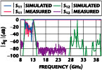
As illustrated in Figure 1 , in a symmetric corrugated waveguide filter, symmetric modes such as TE10 mode do not couple with asymmetric modes such as the TE20 mode. The two groups of mode propagate down the filter without interference. This is the basic principle in designing the low pass filter: to have high attenuation over a particular frequency band for power propagating in the TE10 mode and offer little or no attenuation to the TE20 mode. Since there is no coupling between the TE10 and the TE20 modes, a very clean second harmonic rejection band is created. This characteristic is demonstrated in Figure 2 , in which a typical corrugated waveguide filter of Ku-band is simulated from 8 to 40 GHz and measured from 8 to 26 GHz. No spurious second harmonic mode can be found in the frequency band of 14 to 26 GHz in the results of both simulation and measurement. The same response can also be observed if one end of the filter is connected with an H-plane bend.
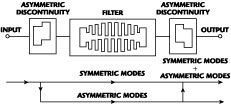
The response will be significantly changed when the filter is measured in a complex microwave system where asymmetric junctions are connected to each end of the filter because of multiple mode couplings. The input power in the TE10 mode will be coupled into the TE20 mode by an asymmetric discontinuity at the input port. The power in the TE10 and TE20 modes propagate independently in the filter. If there is no asymmetric discontinuity at the output port of the filter or within the filter, the measured rejection response for the TE10 mode will be the same as that of an isolated filter. However, if there is an asymmetric discontinuity, such as an H-bend at the output end of the filter, the power in the TE20 mode will be partially coupled to the TE10 mode. When the second mode coupling occurs, the second harmonic mode will appear in the frequency band in which the power in the TE10 mode has been suppressed. This physical interpretation is illustrated in Figure 3 .
Simulation Scheme and Verification
|
|
|
Fig. 3 The multiple mode couplings in a corrugated waveguide filter with asymmetric discontinuities at the input and output ports. |
Having understood the mechanism of the hidden spurious harmonic modes, the following simulation scheme can be proposed to predict the spurious modes. In the simulation, two asymmetric junctions must be added to the filter simulation model, one at each end of the filter to excite the multiple mode couplings. The junctions can simply be asymmetric junction offsets, if the attenuation band is of interest, or H-plane waveguide bends designed for the pass-band, if both the pass-band and attenuation bands are of interest.
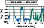
To verify the theoretical interpretation and proposed simulation scheme, the original filter is simulated and measured again with H-plane waveguide bends at each end of the filter. A full-wave modal analysis for the H-plane waveguide bends is used in the simulation.2 A measurement was carried out over a wide frequency band from 8 to 40 GHz. In order to ensure the measured signal is the TE10 mode, the wide frequency band is divided into four sub-frequency bands, namely, 8 to 15 GHz, 15 to 18 GHz, 18 to 26 GHz and 26 to 40 GHz. The WR75 waveguide used for the filter is connected to the dominant mode waveguide corresponding to each sub-frequency band through waveguide tapers. The transmission loss of the simulated and the measured results are superimposed in Figure 4 . Even though the noise floor in the 8 to 15 GHz band is approximately -65 dB and the remainder of the frequency range is approximately -80 dB, the correlation between the simulated and the measured data is excellent. It can be observed that the second harmonic mode is excited both in the measurement setup and in the computer simulation, and can be predicted accurately if an appropriate electromagnetic model is used. In this study, an in-house mode-matching program was used for the simulation and optimization design of the filter.
Conclusion
|
|
|
Fig. 4 The simulated and measured magnitude of S12 of the corrugated waveguide filter with H-plane bends at the input and output ports. |
The hidden spurious harmonic modes in a corrugated rectangular waveguide filter are reported and investigated from both a theoretical point of view and practical measurements. It has been shown that multiple mode couplings occurring at more than one different location in a filter system cause the spurious harmonic modes. An effective simulation scheme for predicting the spurious modes is proposed and verified experimentally through measurements. It has been shown that the hidden spurious mode can be accurately predicted through an appropriate electromagnetic simulation by introducing more than one asymmetric junction in a filter system.
The theoretical interpretation and the simulation scheme are also applicable to other types of symmetrical waveguide filters in which the unwanted asymmetric harmonics can propagate through the filter. To suppress the spurious second harmonic mode one can use asymmetric filter structures and maximize the attenuation band with intensive optimization, or use ridged waveguide filters, in which the second harmonic mode cannot propagate through the filter.
References
1. G. Matthaei, L. Young and E.M.T. Jones, Microwave Filters, Impedance-matching Networks and Coupling Structures , Artech House Inc., Norwood, MA, 1980.
2. R.H. MacPhie and K.L. Wu, "A Full-wave Modal Analysis of Arbitrarily Shaped Waveguide Discontinuities Using the Finite Plane-wave Series Expansion," IEEE Transactions on Microwave Theory and Techniques , Vol. 47, No. 2, February 1999, pp. 232-237.
Ke-Li Wu received his BS and MEng degrees from Nanjing University of Science and Technology (China) in 1982 and 1985, respectively, and his PhD degree from Laval University (Canada) in 1989. From 1989 to 1993 he was with the Communications Research Laboratory, McMaster University, as a research engineer and a research group manager. He joined the Corporate R&D Division, COM DEV International, Canada, in March 1993, where he was a principle member of the technical staff in charge of developing advanced electromagnetic design software for various microwave subsystems for communication satellite and wireless communications. Dr. Wu has been an associate professor in the department of electronic engineering at The Chinese University of Hong Kong since October 1999. He has published widely in the areas of EM modeling and microwave and antenna engineering, and holds one Canadian patent and one US patent. He was a recipient of the URSI Young Scientist Award in 1992. He was awarded COM DEV's Achievement Award in 1998. His current research interests include all aspects of numerical methods in electromagnetics, passive microwave circuits, and interconnections and LTCC integrated RF modules.
Gordon McDonald received his BSc and PhD degrees from Heriot Watt University, Scotland, in 1975 and 1981, respectively. He joined Plessey Radar, IOW, England, in 1975 as a microwave engineer and worked on antenna measurements and phase shifter design for shipbourne radar applications. In 1979 he worked for RACAL MESL and developed PIN diode and ferrite control components. Since 1981 he has been employed by COM DEV International, and has held positions as program manager, antenna/ferrite department manager and has been a principle member of the technical staff. He is currently on a two-year assignment as engineering manager, COM DEV Wireless, Suzhou, China.