
Technical Feature
Orthogonal Frequency Division Multiplex Overview
Ali Zamanian
Fluor Corp.
Wireless broadband, also called wireless cable, was developed to provide local access to small business and residential users for the delivery of high quality digital data, video and voice services. Orthogonal frequency division multiplex (OFDM) is a modulation method that was developed around Data Over Cable Service Interface Specifications (DOCSIS). The goal of this article is to explain the OFDM concept and the improvement gained by applying space diversity techniques to the OFDM system in a multi-path fading environment.
Historical Background
Multi-carrier modulation (MCM) is a technique whereby a channel is partitioned into a set of independent sub-channels or sub-carriers. MCM is not a new development and has been known since the mid-1950s. It has been the subject of extensive work as far back as the mid-1960s at Bell Telephone Laboratories. MCM was used in military HF communication systems such as the KINEPLEX system from Collins Radio Co. and Western Electric narrowband frequency shift keying (FSK) teletype systems.
Originally multi-carrier systems were implemented by generating a number of carriers using separate local oscillators. The receivers required narrow bandpass filters to separate each individual sub-carrier from all others, prior to demodulation. These early implementations were bulky, costly and would be impractical today.
In recent years DOCSIS, which is based on the MCM, was developed in North America and approved by the International Telecommunication Union (ITU) in March 1998. DOCSIS was developed to create a standard for the transmission of high speed data over cable networks.
The rapid increase in digital signal processing with the advent of high speed very large scale integration (VLSI) technology and the implementation of the fast Fourier transform (FFT) has made OFDM feasible and, in turn, very successful. In fact, OFDM became even more attractive when FFT was introduced to generate the different individual orthogonal carriers.
MCM/OFDM
|
|
|
Fig. 1 MCM principle. |

MCM is the principle of transmitting data by dividing the data stream into a large number of parallel bit streams (typically more than 500), each of which has a much lower bit rate, and by using these parallel data sub-streams to modulate individual sub-carriers. Each sub-carrier occupies only a small fraction of the total transmission band and overlaps only with immediately adjacent sub-carriers. The larger the number N of sub-carriers, the longer the symbol period and the less susceptible the system is in a multi-path fading environment. However, N is, in practice, restricted by the limitations in the filtering process, computational time, the available transmission bandwidth of the channel and the Doppler frequency (in a mobile environment). Figure 1 shows the MCM concept.
OFDM is a special modern form of MCM with densely spaced sub-carriers and overlapping spectrum of the adjacent carriers. OFDM abandoned the use of steep bandpass filters and, instead, time domain waveforms are chosen such that mutual orthogonality is ensured even though adjacent sub-carrier spectrums may overlap.
Orthogonality
Orthogonality is defined as "pertaining to or composed of right angles." Orthogonality is related to the fact that two vectors in-space may intersect at a right angle and are thus perpendicular geometrically. Orthogonal signals simply means that the signal states are independent of each other. For example, frequency modulation and amplitude modulation signals on the same carrier can be detected without interfering with each other. Thus, the two signals can be termed "orthogonal."
Another example is assuming that in a system using binary FSK modulation, a zero (0) corresponds to one frequency shift (tone) and a one (1) corresponds to another. This FSK binary signal can be detected with two properly tuned filters. The filter for digit 1 does not respond to a digit 0 signal, and vice versa. This FSK is called binary orthogonal signaling.
In OFDM, the orthogonality is provided by pulse forming of the carrier, which makes the spectrum of each carrier a null at the center frequency of each of the other carriers in the system. This enables each sub-carrier to be extracted from the set with no interference from the other sub-carriers. The sub-carriers can be spaced as close as theoretically possible. The task of pulse forming and modulation can be performed by a simple inverse fast Fourier transform (IFFT).
Fourier Transform and Inverse Fourier Transforms
The function of the Fourier transform can be compared to a prism that breaks down white light into its component bands of colored light. The Fourier transform is used to separate a signal into its constituent frequencies. In fact, the Fourier transform can be used to solve a variety of problems by analyzing the component frequencies of a signal or any system. Among the numerous applications of the Fourier transform are digital signal processing in OFDM systems.
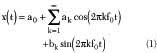
The Fourier transform is a mathematical technique for converting any time domain function into a frequency spectrum. It is based on the fact that it is possible to take any periodic function of time x(t) and decompose it into an equivalent infinite summation of sine and cosine waves with frequencies that start at 0 and increase in integer multiples of a base frequency f0 = 1/T, where T is the period of x(t). The Fourier transform equation is
The Fourier transform (FT) decomposes or separates a waveform or function into sinusoids of different frequencies which sum to the original waveform. It derives the constituent sine waves and their respective amplitudes and frequencies. Therefore, a time varying signal may be expressed as the sum of a series of sine and cosine waves. For example, to send a square wave digital signal is the same as sending a series of sine waves.
|
|
|
Fig. 2 FFT of a modulated sub-carrier. |

Thus, FT basically translates a signal from the time domain where it is expressed as a series of time events to the frequency domain where it is expressed as the amplitude and phase of a particular set of frequencies. The inverse FT (IFT) performs the reciprocal operation.
The fast Fourier transform (FFT) allows one to quickly calculate the Fourier transform and the inverse Fourier transform of a real or complex data set.
|
|
|
Fig. 3 Multiplexed frequency domain serial signal. |

A sine wave of finite duration T can be transformed into an equivalent sinc pulse in the frequency domain. It can be seen in Figure 2 that the sinc pulse has zero crossings spaced 1/T apart, T being the symbol duration in the time domain. Hence, if a sub-carrier spacing of 1/T is used between the sub-carriers, the peaks will be located on all the other sub-carriers spectra crossings. Although there will be spectral overlaps among the sub-carriers, they will not interfere with each other. In other words, they maintain spectral orthogonality. This concept is shown in Figure 3 . A detailed understanding of orthogonality in OFDM shows that the bandwidth of a modulated carrier has a so-called sinc shape (sinx/x) with nulls spaced by the bit rate.
OFDM System
OFDM is basically a frequency division multiplexing technique, whereby the channel's frequency band is divided into N smaller frequency bands, each spaced at the symbol rate, making the sub-carriers orthogonal.
On the transmitter side, one high speed data signal is divided into tens or hundreds of lower speed data streams. Each of these low data streams (which can be digitized voice, video or computer data) modulates one of the sub-carriers, which are all transmitted in parallel. The modulation of each sub-carrier is some form of quadrature amplitude modulation (QAM), QAM, 16 QAM or 64 QAM, for example. In OFDM, a block of data is converted into a parallel form and mapped into each sub-carrier. Thus, they become the frequency domain symbols. To get the time domain signal again, IFFT is applied. These time domain symbols are multiplexed into a serial signal and the output from the IFFT is placed at the appropriate frequency for transmission.
Comparing OFDM with single channel carrier modulation (SCCM) it can be said that SCCM carries the information in a serial manner, whereas OFDM carries the information in a parallel manner. Figure 4 shows the block diagram of an OFDM transmitter.
|
|
|
|


In an OFDM system, each sub-carrier is shaped to be orthogonal to all the other sub-carriers. With this arrangement, even adjacent sub-carriers can overlap without interfering with each other. Therefore, this eliminates the need for guard bands between them. Each sub-carrier is orthogonal to each other while the frequency spectrum overlaps. Since the frequency spacing between the sub-carriers is minimum in OFDM, it offers high spectral efficiency. In OFDM systems, the relationship between all sub-carriers must be carefully controlled to maintain their orthogonality. The IFFT performs the transformation very efficiently, and provides a simple way of ensuring that the produced carrier signals are orthogonal. After OFDM modulation, a guard interval is inserted to suppress inter-symbol interference (ISI) caused by multi-path. This guard interval is also called a cyclic prefix.
The receiver performs the reverse function of the transmitter. In the receiver, the FFT transforms the time domain signal into its equivalent frequency spectrum. The block diagram of an OFMD receiver is shown in Figure 5 .
Cyclic Prefix
|
|
|
Fig. 6 Cyclic prefix. |

The technique for combating the channel impairments caused by multi-path involves the use of a guard time sequence called cyclic prefix. The cyclic prefix is a copy of the last part of the OFDM symbol of length equal to or greater than the maximum delay spread due to multi-path. The cyclic prefix is mapped on the front of the OFDM symbol to serve as guard interval for inter-symbol overlap occurring during the transmission, as shown in Figure 6 . The parallel-to-serial conversion is made after the mapping of the cyclic prefix in the transmitter.
At the receiver, the so-called guard interval is removed. As long as the length of this interval is longer than the maximum channel delay, all multi-path overlap of previous symbols are removed and the orthogonality is preserved. Of course this is not done for free. By preceding the useful symbol length by the guard interval, some parts of the signal that cannot be used for transmitting information are lost. Although the insertion of a cyclic prefix imposes a penalty in terms of transmitted power and available bandwidth, it is well agreed that it is a compromise between performance and efficiency in the presence of ISI.
Vector Orthogonal Frequency Division Multiplex
Diversity antennas are a proven technique for combating the effects of multi-path. An OFDM system using spatial diversity is called vector orthogonal frequency division multiplexing (VOFDM). A VOFDM system using spatial diversity takes advantage of the multiple RF signals received with different phases and amplitudes, and combines them to make a reliable signal in the non-line-of-sight environment. A receiver, with two antenna feeds at the end-user premises, receives incoming signals from diverse paths and combines them so as to achieve the highest possible signal-to-noise level.
Cisco Systems has proposed a VOFDM system in which the combiner examines each of the signals received from the antennas, analyzes sub-carrier by sub-carrier and uses the information from both feeds to reconstruct a single signal for each sub-carrier with higher signal-to-interference ratio, resulting in lower error rate.
Adaptive Modulation in OFDM
For simplicity, most multi-carrier systems use a fixed modulation scheme for all sub-carriers. In systems that use a fixed modulation scheme, the type of modulation for sub-carriers must be selected to provide an acceptable bit error rate (BER) under the worst channel conditions. This results in using BPSK or QPSK with a spectral efficiency of 1or 2 bits/s/Hz, respectively.
In a point-to-multipoint OFDM system, it is possible to vary the modulation scheme depending on the signal quality received at the remote end-user station. The type of modulation used can include BPSK, QPSK, 8 PSK, 16 QAM or 64 QAM. When the remote end-user station experiences a low signal-to-noise ratio, a lower level of modulation such as QPSK performs better than a higher level one. Each modulation scheme provides a trade-off between channel condition (BER) and spectral efficiency.
Depending on the acceptable BER, the type of modulation scheme can be automatically selected to provide the maximum spectral efficiency for that BER. This adaptive modulation technique applies higher order modulation levels when the radio channel is good and lower levels of modulation when the channel is poor. Consequently, adaptive modulation can significantly increase the spectral efficiency of the overall system.
OFDM Advantages
The major advantages that an OFDM system offers over a single carrier system are spectral efficiency, immunity to multi-path propagation and less sensitivity to frequency selective fading.
Spectral Efficiency
In an OFDM system, the orthogonality between adjacent sub-carriers allows spectrum overlap of these sub-carriers, eliminating the need for guard bands between them (except the guard bands needed at the edges of the occupied frequency band). This results in a very high spectral efficiency.
Immunity to Multi-path Propagation
|
|
|
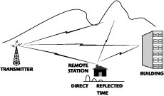
Fig. 7 Multipath signal paths. |
Inter-symbol Interference
Radio waves travel in space at a rate of 186,000 miles per second, taking 5.2 microsecond per mile. As shown in Figure 7 , because of the reflection of the radio waves from buildings, hills and other obstructions, multiple replicas of the transmitted signal, each traveling a path of different length, can arrive at the receiver at slightly different times (delay spread) with different phase and amplitude.
In digital transmission systems, the data pulses are shaped in symbols that are more suitable for transmission, and these symbols modulate the carrier. In a broadband system the information bit rate (symbol rate) is high and these symbols are spaced closely in time. At the receiver, the symbols associated with delayed reflected radio waves interfere with the next few symbols transmitted. This type of interference is called inter-symbol interference (ISI). ISI makes it very difficult to extract the original information from the received signals.
In OFDM, one high speed data signal is divided into tens or hundreds of lower speed signals, which are all transmitted in parallel by using a large set of sub-carriers. The bit rate of each parallel bit stream modulating one of the many sub-carriers is low, so each symbol has a correspondingly longer duration, larger than the expected multi-path delay spread. The time between symbol rates is more than the delay spread of the reflected signals, and the symbols associated with delayed reflected radio waves arriving at the receiver antenna fall in the guard time intervals and cannot interfere with the next symbols transmitted. This makes the OFDM system highly tolerant to multi-path interference.
As an example, assuming a scenario where a system has a transmission data rate R equal to 4 Mb/s and assuming an environment where the maximum delay spread is 55 ms.
The time interval between symbols is T = 1/R = 0.25 ms.
For the single carrier system, those reflected symbols arriving within 55 ms will cause interference with the next 220 symbols (ISI of 55 ÷ 0.25 = 220).
Removing this interference in the receiver is very difficult.
Now assume a multi-carrier system with 1024 sub-carriers. The data rate modulation for each carrier will be approximately 3.9 kb/s and the time interval between symbols is T = 1/R = 256 ms.
Therefore, those reflected symbols arriving within 55 ms will not cause interference with other transmitted symbols. This is the main reason why the multi-carrier approach has become so popular.
Frequency Selective Fading
In a broadband system such as OFDM, the effect of multi-path propagation on different frequency components (or sub-carriers in OFDM) is different. To understand selective fading, what happens to two frequency components or sub-carriers within a frequency band on their trip from transmitter to receiver can be examined. If these frequencies are close to each other, then the different propagation paths within a multi-path environment have approximately the same electrical length for both frequencies, and their amplitude and phase variation will be very similar, that is, highly correlated. However, as the separation of these frequencies increases, the behavior at one frequency becomes uncorrelated with that of the other frequency because the differential phase shifts along the various paths are quite different. The decrease of correlation depends on the time delays between the components received from different paths.
Frequencies that occupy a bandwidth greater than that over which the frequency components are affected in a similar way will become distorted. This is because the amplitudes and phases of the frequencies making up the signal at the receiver are not the same as they were in the transmitted version. This phenomenon is known as frequency selective fading.
Improvement to Frequency Selective Fading
In a multi-path radio channel environment, frequency selective fading can result in a large variation in the received power of one or a few sub-carriers. For a channel with no direct signal path, this RF signal fading can be as much as 30 dB in received power, resulting in a low signal-to-noise ratio. Because of the lower signal-to-noise ratio, the error rate will be increased during fading. Since the information data are distributed among many sub-carriers, affected information in one or a few sub-carriers can be recovered by using forward error detection and correction coding. In this way the data received in error or lost by this type of interference can be recovered.
Conclusion
An OFDM system using spatial diversity takes advantage of the multiple RF signals received with different phases and amplitudes, and combines them to make a reliable signal in the non-line-of-sight environment. The major advantages that an OFDM system offers over a single carrier system are spectral efficiency, immunity to multi-path propagation and less sensitivity to frequency selective fading.