
Application Note
Fast Design of Cross-coupled Filter Substructures
Cross-coupled narrow bandpass filters with asymmetric transmission zeros can be realized in cascaded tri-section topology.1,2,3 Each tri-section creates a single transmission zero below or above the passband. The realization of resonator tri-sections is relatively difficult due to the interaction between the couplings. This article shows how three-dimensional electromagnetic (3D-EM) analysis, together with extraction of an equivalent circuit model, can speed up the realization process of cascaded tri-section bandpass filters.
Dieter Pelz
RFS Australia
Kilsyth, Victoria, Australia
In the realization stage of a narrow bandpass filter design, a given set of coupling values (coupling matrix) must be translated into the physical domain in the form of coupling apertures, loop- or probe-coupling dimensions. A special difficulty exists in resonator tri-sections where coupling exists between all three resonators (Figure 1 ). At the same time, tri-sections offer unique features as they can realize a single finite frequency transmission zero, located either below or above the filter's passband. The normalized impedance matrix of a narrowband tri-section can be written as
 (1)
(1)
where

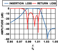
and the Xv are constant reactances representing the offset of each resonator from the filter's nominal center frequency. Typical response curves of a tri-section are given in Figure 2 . Cascaded tri-section filters are attractive because they allow a quasi-independent fine-adjustment of transmission zeros. However, given the usually large diameters of the high Q resonator cavities (either TEM or dielectric resonators), the size of the coupling apertures tends to be very large, so that there is only a relatively small residual center "post" which is common to all resonators. Changes in the dimensions of this central post affect all coupling factors and hence the design becomes quite difficult. 3D-EM analysis can analyze such filter structures accurately. At the same time, there are very simple and accurate equivalent circuits which can be matched to a given two-port S-matrix obtained from 3D-EM analysis, as shown in Figure 3 .
|
|
|
|
Fig. 1 Three-dimensional EM model of a resonator tri-section that is part of a multi-resonator filter. |
Fig. 2 Typical response curves of a narrowband resonator tri-section filter substructure. |

The Process
The fundamental principle of the process is that a 3D-EM simulation-generated S-matrix contains all the information about a suitable associated equivalent circuit. 3D-EM simulation models of the proposed filter substructures can be constructed relatively easily. Initial dimensions of coupling apertures are found from experience or by simulation experiment. The same is true for the input and output coupling elements. Coarse resonator tuning of the 3D model is required; however, there is no need for producing good return loss responses. The given substructure does not have to have defined two-port properties as long as it realizes the desired coupling factors at the desired filter passband frequencies. The validity of separating a tri-section from the remainder of the overall filter is given for narrowband filters with relatively weak coupling between resonators.
S-matrix Identity
|
|
|
Fig. 3 Equivalent circuit of a cascaded tri-section filter. |

With correct element values, a suitable equivalent circuit has the same two-port S-parameters as obtainable from a 3D-EM analysis. It is hence valid to write that
[S]3D EM analysis - [S]Equivalent circuit = 0 (2)
The S-matrix of the equivalent circuit is a function of the circuit element parameters. For a two-port network, four S-parameters exist which can be utilized to match a given equivalent circuit to EM simulation S-parameter data. State-of-the-art circuit analysis packages provide automatic S-parameter fitting facilities; however, it is also relatively easy to set up such fitting facilities manually. Optimization is used to minimize the S-matrix differences, where the variables are the circuit elements. It is important to refine the circuit model, so as to include major real-world effects. The quality of the extracted equivalent circuit is marked by a very small residual difference between the S-parameter responses, as shown in Figure 4 .
Accuracy Requirements
|
|
|
Fig. 4 Extracted circuit response vs. 3D-EM simulation. |

The accuracy requirement for the 3D-EM simulation is moderate. It was found that even a relatively rough field solution provides S-parameter data, which contains accurate information on the coupling factors between the resonators. Refinement of the field solution mainly affects the resonator frequencies, which are only of secondary interest, because the coupling factors are not strongly frequency dependent. In the impedance matrix (Equation 1) even the coupling impedances are frequency independent, which is valid in the narrowband case for frequencies in and near the filter passband.
Accuracy of the Method The parameters of different nine-pole and seven-pole TEM-resonator bandpass filters realized in the 900 and 1800 MHz range were established by extraction from measured S-parameter data. Subsequently the filter's tri-section geometries were analyzed by 3D-EM simulation (using Agilent HFSS). This involved the inclusion of an additional port probe coupling on one side of the structure, where there would normally be an adjoining resonator. The S-parameter data generated by the EM simulator was then used for extracting the filter parameters of the tri-section substructure. Table 1 shows the excellent agreement between the EM simulation-extracted filter parameters and the measurement extracted data. The field distortion caused by the additional port coupling element obviously has only a negligible effect.
|
Table 1 | ||
|
Coupling Value |
Prototype Measurement-derived Value |
3D EM Tri-section Simulation Extracted Value |
|
k12 |
0.0200 |
0.0201 |
|
k23 |
0.0126 |
0.0123 |
|
k13 |
0.0133 |
0.0134 |
Conclusion
It has been established that 3D-EM analysis of multi-resonator filter substructures with equivalent circuit extraction can yield accurate information on the couplings between resonators. Tri-sections can therefore be designed by iterative EM analysis with subsequent parameter extraction. This technique replaces lengthy prototype iterations and speeds up the filter realization process. Modifications of the structure geometry can be carried out during the 3D-EM modeling and their effect on the filter parameters can be accurately obtained within minutes. The described method also greatly reduces the need for coupling adjustment means.
References
1. Rafi Hershtig, Ralph Levy and Kawthar Zaki "Synthesis of Cascaded Trisection (CT) Dielectric Resonator Filters," EuMC, Jerusalem, 1997.
2. C. Bell, R. Levy, A. Atia and W.C. Tang, Microwave Filter Synthesis and Equivalent Circuit Extractions , 2000 IEEE MTT-S International Microwave Symposium, WSC Workshop Notes.
3. N. Yildirim, M. Karaaslan, Y. Sen and O.A. Sen, "Filpro: A Synthesis and Circuit Transformations Software for Filters and Multiplexers," Web Page http://www. eee.metu. edu.tr/~nyil).
Dieter Pelz (Dipl. Ing., Germany, 1975) joined RFS Australia in 1995 after working for both SEL-Alcatel and Rohde & Schwarz. He has been working in the field of microwave filter synthesis and design for over 20 years. He holds four patents on filters and diplexers. Mr. Pelz can be reached via e-mail at dpelz@compuserve.com.