
TECHNICAL FEATURE
Design of a Planar Microstrip Balun at S-band
An innovation for the Marchand balun model is presented. The structure of the designed planar microstrip matching circuit is fairly simple, practical and easily fabricated without requiring complex multiple metal or dielectric layers. Moreover, the designed balun performs well. The measured phase difference between the balance ports was within 180° ±3° from 1.9 to 3.9 GHz and the magnitudes of S21 and S31 are fairly close to 3 dB from 2.4 to 3.2 GHz. The design and simulation of the planar microstrip balun show good agreement with the measured results.
Jwo-Shiun Sun and Tsung-Lin Lee
National Taipei University of Technology
Department of Electronic Engineering
Taipei, Taiwan, ROC
A balun, an unbalanced to balanced line transformer, was first proposed by Marchand1 in 1944. Because of its output-balanced characteristic with a phase difference of 180°, it is a significant component for many different applications, including mixers,26 balanced amplifiers79 and antennas.1014 Because of their wide bandwidth and inherent outputs of equal amplitude with 180° phase difference, many different implementations of baluns such as log periodic baluns15 , three line baluns,16 N-section half-wave baluns,17 microstrip taper baluns18 and lumped element baluns1920 are used in microwave circuits.
A balun is a circuit that transforms from an unbalanced input to balanced outputs or vice-versa. It is also an impedance transformer that can produce two different signal levels with 180° phase difference. Generally, baluns can be classified into active or passive types. The design criteria for baluns are better isolation, impedance matching, balanced to unbalanced transformation and lower noise interaction in-between ports.
Active baluns1316 are constructed with active elements (FETs) with a common source or common gate configuration to achieve impedance matching. Generally, an active balun with output gain can decrease an oscillator's input gain requirement in mixer applications. However, a FET is an active device with DC power dissipation and higher noise level. Passive baluns are constructed with coplanar transmission lines, coaxial lines or microstrip lines. Passive baluns are widely used in either mixers or power amplifiers. With the advantage of a compact configuration combining two identical coupled lines with different termination, a passive structure balun, with 180° phase difference at S-band (24 GHz) of the Marchand model, is studied in this article.
RESULTS AND DISCUSSIONS
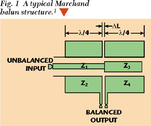
Figure 1 shows a typical Marchand balun structure1 with characteristic impedances Z1 , Z2 , Z3 and Z4 . The electrical length of each transmission line is λ/4 ( = 90°). The signal transmitted from the unbalance port to the two balance ports travels λ/4 and 3λ/4 wavelengths. Therefore, the output phase difference between the balance ports is 180° (3λ/4 λ/4 = λ/2). ΔL is the narrow distance between the balanced output ports.
|
|
The modification shown in Figure 2 has an unbalanced input centerline with four identical microstrip lines of λ/4 length to obtain a bilateral balanced output. This designed balun consists of a signal input at an unbalanced port and ±90° phase difference at the bilateral balanced outputs with a phase difference of | 21 31 | = 180°. Experience shows that a design for 3 dB coupling will require rather narrow spaces S1 and S2 between the microstrip lines, which increase the complexity for its implementation.
|
|

The Microwave Office Program of Applied Wave Research© was used in the design and analysis of the balun. Figure 3 shows the circuit model of the design on an FR4 substrate. The simulation results shown in Figure 4 demonstrates that the power levels |S21 | and |S31 | are close to 3 dB with a variation of less than 0.3 dB from 1.9 to 3.9 GHz. The return loss |S11 | is greater than 15 dB. The phase response of S21 and S31 with 180° difference is shown in Figure 5.
|
|


An HP 8720C network analyzer was used for the experimental measurements. The output of S21 and S31 are designed for 3 dB coupling and the measured experimental results shown in Figure 6 are S21 = 3.186 dB and S31 = 3.478 dB at 2.4 GHz. The measured results in Figure 7 show the phase difference | 21 31 | to be 180° ±3° from 1.9 to 3.9 GHz. Figure 8 shows a picture of the actual balun. The measured results and simulated data are in very good agreement.
 |
 |
|
| |

CONCLUSION
A modification of the Marchand balun model is presented and the designed planar microstrip circuit is fairly simple and practical without complex layers. The designed balun exhibits good performance. The measured phase difference between the balance ports was within 180° ±3° from 1.9 to 3.9 GHz and the magnitudes of S21 and S31 are close to 3 dB from 2.4 to 3.2 GHz. Experimental results substantiate this design with good agreement between measurement and simulation data.
ACKNOWLEDGMENTS
The authors wish to thank president William Wang, C.P. Wang, K. Chang, H.J. Chen, N. Chang and D. Chung of Global PCS Inc., Hsinchu, Taiwan, ROC, for their help and suggestions.
References
1. N. Marchand, "Transmission-line Conversion Transformers," Electronics, Vol. 17, December 1944, pp. 142146.
2. S.A. Mass, Microwave Mixers, Second Edition, Artech House, Norwood, MA, 1993.
3. K.C. Tsai and P.R. Gray, "A 1.9 GHz, 1-W CMOS Class-E Power Amplifier for Wireless Communications," IEEE Journal of Solid-state Circuits, Vol. 34, No. 7, July 1999, pp. 962970.
4. M.C. Tsai, K.W. Chang, M. Ventresca, R. Binder, R. Waterman and D. Danzlilio, "A Compact Wideband Balanced Mixer," IEEE IMS Digest, Vol. 1, 1994, pp. 58.
5. Y.H. Lin and Y.J Chan, "2.4 GHz Single Balanced Diode Mixer Fabricated on Al2O3 Substrate," IEEE Conference Asia Pacific Proceedings, Vol. 2, 1999, pp. 218221.
6. A.M. Pavio, R.H. Halladay, S.D. Bingham and C.A. Sapashe, "Double Balanced Mixer Using Active and Passive Techniques," IEEE Transactions on Microwave Theory and Techniques, Vol. 36, No. 12, December 1988, pp. 19481957.
7. I. Takenaka, K. Ishikura, H. Takahashi, K. Asano, J. Morikawa, K. Satou, K. Kishi and K. Hasegawa, "L/S-band 140-W Push-pull Power AlGaAs/GaAs HFETs for Digital Cellular Basestations," IEEE Journal of Solid-state Circuits, Vol. 34, No. 9, September 1999, pp. 11811187.
8. C.S. Lee, M.G. Kim, J.J. Lee, K.E. Pyun and H.M. Park, "A Low Noise Amplifier for a Multi-band and Multi-mode Handset," IEEE RFIC Digest, 1998, pp. 4750.
9. P. Vizmuller, RF Design Guide Systems, Circuits and Equations, Artech House, Norwood, MA, 1995, pp. 6978.
10. M.C. Tsai, "A New Compact Wideband Balun," IEEE IMS Digest, 1993, pp. 141143.
11. S.A. Maas, Microwave Mixers, Second Edition, Artech House, Norwood, MA, 1993, pp. 237248.
12. S.A. Maas, M. Kintis, F. Fong and M. Tan, "A Broadband Planar Monolithic Ring Mixer," IEEE Microwave and Millimeter-wave Monolithic Circuits Symposium, 1996, pp. 5154.
13. S.A. Maas, Microwave Mixers, Second Edition, Artech House, Norwood, MA, 1993, pp. 255259.
14. G.D. Vendelin, A.M. Pavio and U.L. Rohde, Microwave Circuit Design Using Linear and Nonlinear Techniques, A Wiley-Interscience Publication, 1990, pp. 555579.
15. M. Basraoui and S.N. Prasad, "Wideband, Planar, Log-periodic Balun," IEEE IMS Digest, 1998, pp. 785788.
16. C. Cho and K.C. Gupta, "A New Design Procedure for Single-layer and Two-layer Three-line Baluns," IEEE Transactions on Microwave Theory and Techniques, Vol. 46, No. 12, December 1998, pp. 25142519.
17. K.C. Chai and S. Tokumaru, "Antenna Factors of Half-wavelength Dipole Antennas with Roberts Balun," Electronics and Communications in Japan, Part I: Communications, Vol. 79, No. 9, September 1996, pp. 104112.
18. B. Climer, "Analysis of Suspended Microstrip Taper Baluns," IEE Proceedings, Vol. 135, No. 2, April 1998.
19. H.K. Chiou, H.H. Lin and C.Y. Chang, "Lumped-element Compensated High/Low Pass Balun Design for MMIC Double-balanced Mixer," IEEE Microwave and Guide Wave Letters, Vol. 7, No. 8, August 1997.
20. S.J. Parisi, "180° Lumped Element Hybrid," IEEE IMS Digest, 1989, pp. 12431246..
|
|
 Jwo-Shiun Sun received his BS degree in electrical engineering from National Cheng Kung University (NCKU) in 1983. He received his MS degree and PhD degree in electrical engineering from NCKU in 1988 and 1992, respectively. Dr. Sun is currently a professor in the department of electronic engineering at National Taipei University of Technology, Taipei, Taiwan. His research interests include microwave devices and circuits, microwave dielectric materials,
  Tsung-Lin Lee received his BS and MS degrees in electrical engineering from National Taipei University of Technology, Taipei, Taiwan, in 1998 and 2000, respectively. During the summers of 1998 and 1999 he worked at Microelectronic Technology Inc. His research interests include microwave circuits, CDMA and their applications.