
TECHNICAL FEATURE
A High Efficiency Bow-tie Antenna for Impulse Propagation
An investigation into the problems associated with using modified dipole antennas to propagate temporally short electrical impulses is described. Experimental data is presented which shows that the time domain characteristics of the bow-tie antenna can be improved by reactively tuning the antenna elements. This is achieved by fabricating the elements using thick-film technology. Broadband dipole antennas are widely used in high resolution impulse, ground-penetrating radar systems for the detection of buried ordnance. The improved antenna has its main parameters determined by this application. The performance of the antennas is analysed in frequency and time domains, producing a complete characterisation of the bow-tie. A simple model is provided which gives an explanation for the improved performance.
Roger Clarke
University of Bradford,
Dept. of Electronics & Telecomms
Bradford, UK
When it is required that a single short impulse be transmitted and received (in a high resolution ground penetrating radar (GPR) system, for example) the choice of antennas is essentially restricted to non-dispersive element antennas (dipoles). The antenna must also have some facility to stop it from resonating (ringing) in order to produce useful target data.
Conventional wire dipole antennas are naturally narrow band devices due to the terminal impedance characteristics, as shown in Figure 1. Dipoles can be made much more broadband by using triangular metal plates instead of thin wires as the radiating elements. These dipole variations are called bow-tie or bifin antennas. The impedance plots for bow-tie antennas are much flatter than those for a wire dipole1 , as shown in Figure 2, and hence have a wider bandwidth.
|
|
|


Even though the bow-tie has the required bandwidth to accommodate the spectral content of the impulse, the problem of ringing is still present.2 This problem is usually solved by employing resistive end loading, which takes the form of resistors (200 to 300 Ω) connected between the end of the bow-tie element and a ground plane.
The use of resistive loading is a crude, albeit effective, method of damping the antenna response.3 The disadvantage of this approach is that not only does the reflected signal from the element end get suppressed, but also some of the incident impulse. Hence, the quoted efficiency values for resistively loaded antennas are quite low.
The impedance plot for an antenna usually takes the form of the real and imaginary data curves plotted on the same graph. The resistance and reactance plots show that when a dipole antenna is operating with a CW signal at its resonant frequency, its length is 0.5 λ, the reactive component is zero and the resistive component is approximately 73 Ω. This also applies to bow-tie antennas, but in this case the zero reactance point occurs at less than 0.5 λ due to the element geometry.
However, under impulse conditions the antenna response is different. Ringing occurs because the antenna is only a perfect match over a small part of the spectral range of the impulse. Since the resistance and reactance curves are effectively locked together by virtue of the electrical characteristics and geometry of the antenna elements, it would seem apparent that the only way to stop the ringing is to resistively load the elements.
It would be very useful to have some independent control over the resistive and reactive components of the antenna's impedance. This would allow reactive tuning to be performed, matching the terminal impedance of the bow-tie antenna to the spectral component of the impulse that has the highest amplitude. Under these circumstances, an impulse reflection from the element end would still occur, but no further reflections of any significance would occur from the antenna feed-point.
One way of adjusting the reactance of the antenna element is to change the shunt capacitance to ground. This could only be achieved if the bow-tie antenna has a grounded shield (which is already necessary with a GPR antenna). The capacitance modification can then be implemented by using a high dielectric constant substrate, onto which the element conductor is placed.
Thick-film technology provides the ideal medium in which to optimize the performance of the bow-tie elements. This is because alumina (Al2 O3 ) substrates have a high dielectric constant (εr = 9.5), which increases the capacitance. The metallization (AgPt) is then printed onto the substrate to form the element conductor. Since the metallization thickness can be pre-set with this technique, the electrical characteristics of the element can be optimised both in terms of the capacitance and inductance.4
FABRICATION AND MEASUREMENTS
In order to make a fair comparison between a conventionally implemented bow-tie antenna and its thick-film counterpart, a pair of yellow brass bow-tie elements were fabricated along with a set of thick-film elements with a range of metallization thicknesses. The same backlobe suppression shield (filled with microwave absorber) and balun were used for both element types, as shown in Figure 3. The elements printed onto substrates are shown in Figure 4.
 |
|
|

In order to characterise the antennas both in frequency and time domains, an HP8753A vector network analyzer and an impulse generator were used, respectively. The impulse generator circuit diagram is shown in Figure 5, with its output trace shown in Figure 6.
 |
|
|

A standard set of far-field measurements was performed on both types of bow-ties to characterise them in the frequency and time domains. This enabled the bandwidth, impulse response and input impedance to be measured for each antenna, and thus a direct comparison in performance terms could be made.
RESULTS
The performance assessment of the bow-tie antennas is based on the parameters described earlier. The data shown compares the conventional brass sheet bow-tie antenna with the bow-ties implemented in thick-film. It should be noted that data from only one of the thick-film variants is presented, namely that with the 32 µm metallization, even though many more were characterised. Figure 7 shows the bandwidth data for the resistively loaded brass bow-tie and Figure 8 shows the same data for the thick-film variant.
|
|
|


Figure 9 and Figure 10 show the time domain response for the two bow-tie antennas when excited with a 400 ps rise time impulse. The data were obtained using a fast storage oscilloscope.
|
|
|


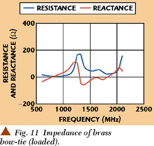
The impedance data for the bow-tie antennas were obtained using the vector network analyzer, and are shown in Figure 11 and Figure 12.
|
|
|

ANALYSIS
The data shown clearly indicates the improved performance of the thick-film antenna on the basis of its time domain response and bandwidth. The ringing is well attenuated and comparable with that of the resistively loaded bow-tie. It is obvious that an additional inverted impulse occurs in the thick-film variant because the element ends are open circuited, which for the reasons stated earlier is not present with the resistively loaded bow-tie. Nevertheless, the impulse amplitude and sharpness of the thick-film variant, which is also evident in the bandwidth data, make it eminently suitable for high resolution GPR work.
If the reactance data for both antennas is examined, it is apparent that the second zero-crossing point is shifted to a lower frequency with the thick-film variant. This new position for the reactance null corresponds to the 1240 MHz spectral peak of the 400 ps impulse. Thus the good match at the antenna terminals provides the mechanism for damping any residual impulse power.
It is clear that this reactance shift is attributable to the extra capacitance due to the substrate. To confirm this, a set of elements was fabricated using a glass/epoxy printed circuit board which has an εr of 4.8. The impedance plot for this example showed a similar effect, but not to the same extent, and the time domain data predictably showed a less favorable response. However, it was still better than that of the brass sheet elements without resistive loading. Other workers have noted a similar effect using ferrite loading of bow-ties.5
In order to demonstrate more clearly the reason for the apparent performance improvement of the thick-film bow-tie over its brass counterpart, it is necessary to develop a model for the antenna element.
MODEL
All the elements produced were dimensionally identical, with the metallization in each case having low resistivity. The only differences electrically between all the bow-tie antennas fabricated was a variation in the resistivity of the element conductors and the dielectric constant of the substrate on which the element conductors were deposited (FR4 PCB, εr = 4.8 and alumina εr = 9.5). In the case of the brass bow-tie elements where no substrate was used, it was assumed that εr was that of free space. In reality this would be slightly higher due to the microwave absorber foam and the non-conducting beam between the element and the copper shield.
In all these structures there is a volume between the element arm and the copper shield, which is filled with a dielectric material, an arrangement that essentially forms a capacitor. This capacitance, combined with the metallization of the bow-tie elements, which has inductance, gives the basis for a lumped element model shown in Figure 13.
|
|

The lumped element model shown is clearly that of a transmission line, which is entirely appropriate since the antenna element is effectively a tapered micro-strip line, driven from one end, with an open circuit at the other end. However, this circuit is also that of a multi-pole low pass filter, both devices having a characteristic high frequency cut-off point.
There were a number of parameters which showed a dependency on the fabrication method requiring further explanation.
Bandwidth
If the bow-tie antenna's bandwidth is viewed in the context of the associated impedance plots, it can be seen that as the frequency decreases from 1000 to 600 MHz, the resistance value approaches zero. Since the total resistance of the antenna element consists of the loss resistance and the radiation resistance (which is required to allow the antenna to radiate), then the element becomes very inefficient. This leads to a diminished amplitude level in the bandwidth data. This characteristic applies to all element antennas when they are regarded as being electrically small (that is, length < λ/4).
The high frequency cut-off and the notches that appear in the bandwidth data are issues where the model can be used with a simulator to fit this measured data. The capacitance and inductance of a selection of the bow-tie elements were measured and used in the simulator. The measured values are shown in Table 1.
|
|
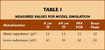
The simulator used was EEsof Touchstone version 1.7. The node configuration chosen was that of a four-pole low pass filter since this order of filter has three passband maxima before cut-off. The measured values of capacitance and inductance were divided between the model elements.
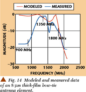
Figure 14 shows the measured and computed bandwidth data for a thick-film antenna element. It is clear from the figure that this fairly basic model for the antenna element provides accurate results. The notch and the cut-off frequency are a very good fit despite the fact that the measured data shows the amplitude falling off from 1600 MHz upwards. This is due to the limited frequency response of the transmit antenna. It is also useful to note that by varying the inductance values in the model, the frequency at which the ripple occurs in the model response can be varied. This is consistent with the measured variation in the frequency at which the notch appears in the measured bandwidth data for the thick-film antennas. This suggests that this variation is attributable to the slight changes in the inductance values that were observed when different thick-film metallization thicknesses were measured.
|
|
It is also worth noting that the parameter values used in the model have not been optimised in order to obtain the accuracy shown. This is important since all the parameters of the model are therefore physical parameter values, which can be traced back to the fabrication process.
Time Domain Response and Input Impedance
There is a clear link between the amount of signal re-reflected from the feed-point and the zero crossing point of the respective reactance plot. This indicates an association with the fabrication method of the bow-tie element.
The measured capacitance values show that the capacitance increases with an increase in the dielectric constant of the substrate. This is entirely expected, since the capacitance is dependent on the relationship C = 0.885KA/d where K is the dielectric constant, A is the plate area in cm2 and d is the distance between the plates in mm.
The extra capacitance has an effect on the impedance data, given by the relationship Xc = 1/2¼fC, which in this case means that the reactance goes capacitive at a slightly lower frequency, with the resistance plot remaining unchanged. The modeling gives a clear indication of how the fabrication method of the antenna elements can be used as a technique for reactive tuning to reduce ringing.
CONCLUSION
It is shown that more power is radiated by the thick-film bow-tie variant than with the conventionally implemented bow-tie with resistive loading. Therefore, it can be said that the thick-film example is more efficient. On the basis of the time domain data, the results from an efficiency calculation are: for the resistively loaded brass bow-tie 33 percent and for the 32 µm thick-film bow-tie 63 percent.
The efficiency figures have to be viewed within the context of the other antenna properties, particularly when used as impulse propagators. Nevertheless, resistive loading is by its nature a fairly inefficient solution, since it requires that a substantial proportion of the signal power be dissipated as heat. On the basis of the data shown, it can be concluded that the thick-film antenna has both good impulse propagating characteristics and higher efficiency. *
References
1. G.H. Brown and O.M. Woodward, "Experimentally Determined Radiation Characteristics of Conical and Triangular Antennas," RCA Rev., 13, 1952, pp. 425452.
2. J. Kraus, Antennas, Second ed., McGraw-Hill, NY, 1988, pp. 5459.
3. K.L. Shlager, G.S. Smith and J.G. Maloney, "Optimisation of Bow-tie Antennas for Pulse Radiation," IEEE Transactions on Antennas and Propagation, AP-42, (7), 1994, pp. 975982.
4. R.W. Clarke and J. Rodriguez-Tellez, "A Comparison of Sheet Metal and Thick-film Cavity Backed Bow-tie Antennas," Proceedings of the 7th International Conference on Ground Penetrating Radars (GPR'98), Kansas, USA, Vol. 1, 1998, pp. 5962.
5. Y. Nishioka, O. Maeshima, T. Uno and S. Adachi, "FDTD Analysis of Resistor Loaded Bow-tie Antennas Covered with Ferrite Coated Conducting Cavity for Subsurface Radar," IEEE Transactions on Antennas and Propagation, AP-47, (6), 1999, pp. 970977.
|
|
 R.W. Clarke received his BSc degree in mathematics and technology from the Open University in 1993 and his PhD degree in electrical engineering from the University of Bradford in 2000. Since 1987 he has worked at the University of Bradford, first as a technician and now as a university teacher. His research interests include antennas and electronic materials.